
Residual stress releasing process device and stress releasing method for manufacturing process of long truss of wing

A technology of residual stress and manufacturing process, applied in the field of residual stress intelligent release tooling and stress release, can solve the problems of vibration force, vibration frequency and vibration direction can not be adjusted, to shorten the quality inspection and assembly cycle, stable vibration, improve The effect of shape accuracy and processing quality

Inactive Publication Date: 2016-03-09
SHANGHAI JIAO TONG UNIV
View PDF7 Cites 4 Cited by
  • Summary
  • Abstract
  • Description
  • Claims
  • Application Information

AI Technical Summary

Problems solved by technology

However, the defect of traditional vibration aging is that the vibration force, vibration frequency and vibration direction cannot be adjusted, so it cannot be well applied to workpieces with variable cross-section, variable thickness and hole features.
[0004] Therefore, those skilled in the art are committed to developing a residual stress release process device and stress release method in the wing stringer manufacturing process to eliminate the defects of traditional vibration aging

Method used


Image

  • Residual stress releasing process device and stress releasing method for manufacturing process of long truss of wing
  • Residual stress releasing process device and stress releasing method for manufacturing process of long truss of wing
  • Residual stress releasing process device and stress releasing method for manufacturing process of long truss of wing

Examples


Embodiment Construction

[0038] The present invention will be described in detail below in conjunction with specific embodiments. The following examples will help those skilled in the art to further understand the present invention, but do not limit the present invention in any form. It should be noted that those skilled in the art can make several modifications and improvements without departing from the concept of the present invention. These all belong to the protection scope of the present invention.

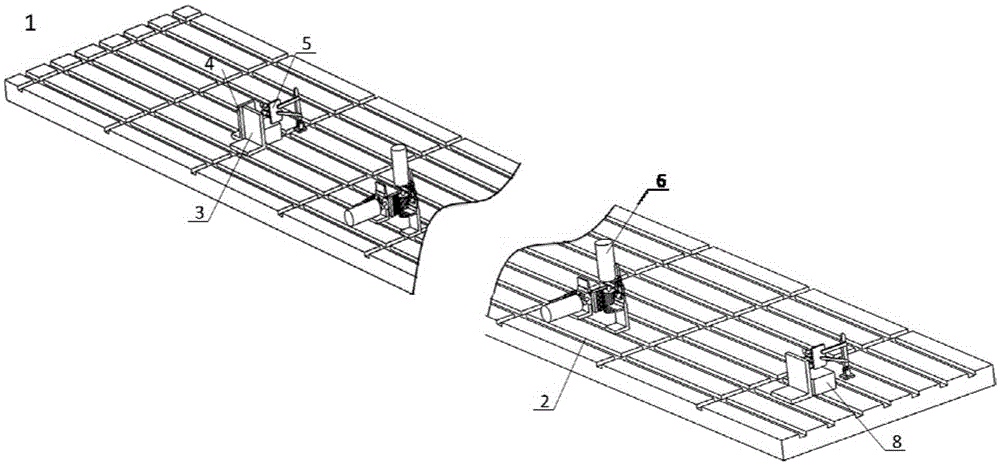
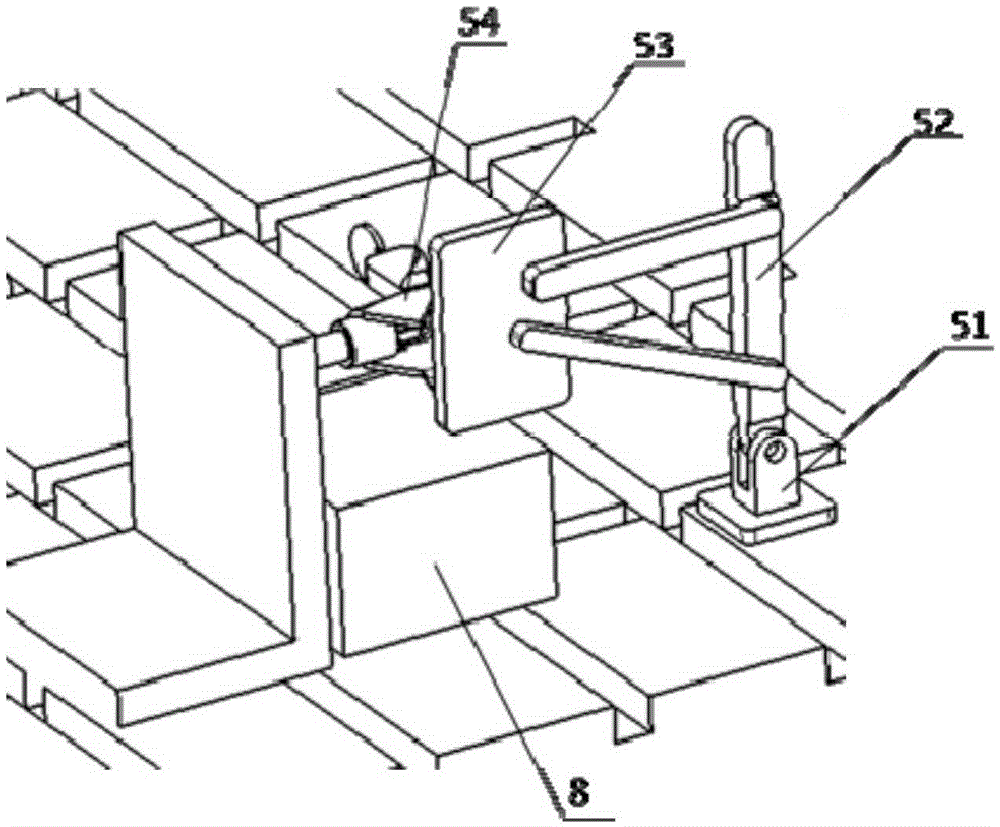
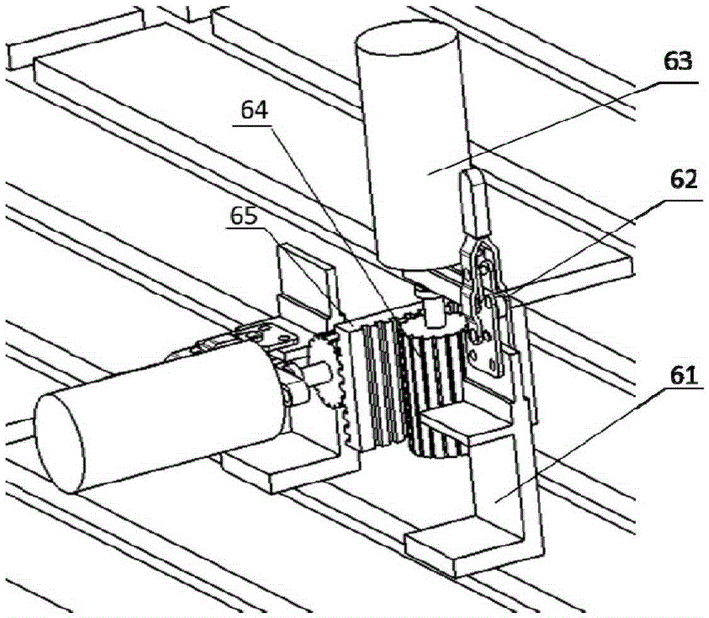
[0039] see figure 1 , the base platform 2 of the tooling 1 is a rectangular structure, the width direction of the base platform 2 is defined as the X direction of the Cartesian coordinate system, the length direction is the Y direction, and the vertical direction perpendicular to the base platform 2 is the Z direction. The X direction is defined as the horizontal direction, the Y direction is defined as the vertical direction, and the Z direction is defined as the vertical direction. The length of...


PUM


Abstract

The invention provides a residual stress releasing process device and a stress releasing method for the manufacturing process of a long truss of a wing, belonging to the field of manufacturing of aerospace components. The residual stress releasing process device comprises a base platform, a bottom vertical positioning block, a transverse positioning block, a longitudinal positioning block, a transverse clamping device and a magnetic vibration device and can release the residual stress in the long truss of the aircraft wing. The invention provides the intelligent residual stress releasing tool applied in the vibration aging treatment process of the long truss of the aircraft wing. The magnetic vibration device can be controlled through an upper computer, so that the vibration frequency, the vibration direction and the size of vibration force of each vibration position can be adjusted. Moreover, a driving member and a driven member in the magnetic vibration device do not directly contact with each other and carry out conduction by relying on magnetic force, so that the residual stress releasing process device has the characteristics of stationary vibration and overload protection, and the damage to the long truss caused by excessive vibration is avoided. The residual stress releasing process device is easy to operate, the long truss can be quickly clamped on the tool, and the effective releasing for the inner residual stress is realized.

Description

technical field [0001] The invention relates to the field of manufacturing aerospace components, in particular to a residual stress intelligent release tool and a stress release method in the manufacturing process of aircraft wing stringers. Background technique [0002] The shape and assembly stress of aircraft wing components directly affect the reliability and safety of the aircraft, so it is necessary to strictly control the quality of its manufacturing process. Among them, the initial residual stress distribution field and initial deformation will be generated in the process of blank preparation, quenching, milling and other processes of aircraft wing stringer. After the wing stringer with initial deformation is assembled with other parts, the residual stress field will change and remain in the component, which will affect the service performance of the product. Therefore, after the machining of the component is completed, by releasing the residual stress inside the com...

Claims


Application Information

Patent Timeline
Patent Type & Authority Applications(China)
IPC IPC(8): C21D10/00
CPCC21D10/00Y02P10/20
Inventor 王华林忠钦刘军
Owner SHANGHAI JIAO TONG UNIV
Learn More