
Preparation method of 3D printed optical-fiber preformed rod with cross sectional structure in optional geometrical shapes

A technology of optical fiber preform and geometric shape, applied in glass manufacturing equipment, manufacturing tools, etc., can solve the problems of difficult preparation, difficult to design and prepare optical fibers with special structure and performance, and achieve low price and cross-sectional shape selectivity Easy, Simple Effects

Inactive Publication Date: 2016-03-09
SHANGHAI UNIV
View PDF4 Cites 3 Cited by
  • Summary
  • Abstract
  • Description
  • Claims
  • Application Information

AI Technical Summary

Problems solved by technology

[0003] In the existing traditional optical fiber preparation process, because the preform deposition temperature is as high as 2000 ° C, the preparation is difficult, so it is difficult to design and prepare optical fibers with specific structures and properties

Method used


Image

  • Preparation method of 3D printed optical-fiber preformed rod with cross sectional structure in optional geometrical shapes
  • Preparation method of 3D printed optical-fiber preformed rod with cross sectional structure in optional geometrical shapes
  • Preparation method of 3D printed optical-fiber preformed rod with cross sectional structure in optional geometrical shapes

Examples


Embodiment 1

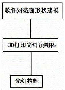
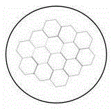
[0014] see figure 1 , the 3D printing method for preparing an optical fiber preform with any cross-sectional structure shape, the operation steps are: 1) Design various cross-sectional geometric shape models required by using 3D printing software, 2) Then use the 3D printing device according to the designed The software model prints out the optical fiber preform model of the required cross-sectional structure geometry, and can print out the optical fiber preform of any shape with various required cross-sectional structures according to the software design, 3) and then draw out various optical fiber preforms. Optical fiber with transmission and conversion characteristics-photonic crystal fiber, or eccentric fiber, or multi-core fiber, or arbitrary polygonal fiber, or its intersecting optical fiber, with various unique optical transmission and conversion properties, will provide optical fiber communication and optical sensing Provide various functional optical fibers with specif...

Embodiment 2

[0017] This embodiment is basically the same as Embodiment 1, and the special features are as follows:

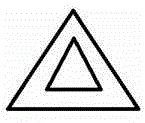
[0018] By using 3D printing software to design an eccentric fiber pattern with a porous cross-sectional structure geometry, and then print the cross-sectional structure as an eccentric optical fiber preform model through a 3D printing device, and then can be drawn with various light transmission and conversion characteristics. Eccentric optical fiber, to produce functional optical fiber with specific performance. Prepare and print an optical fiber preform with eccentricity, and then draw an optical fiber with eccentricity.


PUM


Abstract

The invention relates to a preparation method of a 3D printed optical-fiber preformed rod with a cross sectional structure in optional geometrical shapes. An optical-fiber preformed rod with different cross sectional structures is printed by designing different models and comprises an appearance structure and a core structure, the optical-fiber preformed rod can be further drawn into various special optical fibers with the cross sectional structure in different geometrical shapes and special optical fibers with specific light transmission and transformation properties, such as photonic crystal fibers, eccentric core fibers, multi-core optical fibers, optional polygonal optical fibers and optical fibers with an intersected structure, and the optical fibers have various unique light transmission and transformation properties and can meet the requirements of optical fiber communication and light sensing functions, so that various special functional optical fibers with specific light transmission and transformation properties can be provided.

Description

technical field [0001] The invention relates to a method for preparing an optical fiber preform with an arbitrary geometric shape of a 3D printed cross-sectional structure, which has the characteristics of fast, convenient, uniform, energy-saving, no environmental pollution, and an arbitrary geometric shape of the cross-sectional structure, and can be used to design various optical fiber preforms. Fiber optics with transmission and transformation properties. Background technique [0002] 3D printing technology is a technology based on digital model files, using bondable materials such as powdered metal or plastic, to construct objects by layer-by-layer printing. It has been used in many fields, and is now gradually being used in some products. 3D printing of artificial organs, 3D printing of aircraft parts, and even 3D printing of houses. The technology has applications in industrial design, architecture, automotive, aerospace, dental and medical industries, geographic info...

Claims


Application Information

Patent Timeline
Patent Type & Authority Applications(China)
IPC IPC(8): C03B37/012
CPCC03B37/012
Inventor 陈振宜王廷云庞拂飞文建湘陈娜
Owner SHANGHAI UNIV
Learn More