
Tower crane cargo boom pull rod structure

A pull rod structure and boom technology, which is applied to cranes and other directions, can solve the problems of heavy structure weight, high manufacturing cost and complicated manufacturing of the pull puller, and achieve the effects of convenient and fast manufacturing process, simple structure and fast installation process.

Inactive Publication Date: 2016-03-09
XUZHOU CONSTR MACHINERY
View PDF7 Cites 3 Cited by
  • Summary
  • Abstract
  • Description
  • Claims
  • Application Information

AI Technical Summary

Problems solved by technology

[0003] The disadvantage of the above structure is that there are many pulley blocks, heavy structure, complicated manufacture, and high cost. The specific description is as follows: 1. Since there are two pulley blocks on the top of the tower and one on the puller, the number of pulley blocks is large and the cost is high; 2. Due to The structure of the plate puller is heavy and has many parts, resulting in high manufacturing costs; 3. There are many structural parts and complicated installation

Method used


Image

  • Tower crane cargo boom pull rod structure
  • Tower crane cargo boom pull rod structure
  • Tower crane cargo boom pull rod structure

Examples


Embodiment Construction

[0023] The present invention will be further described below in conjunction with accompanying drawing.

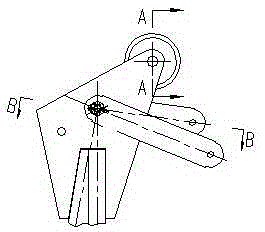
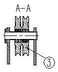
[0024] Such as Figure 8-Figure 10 As shown, the present invention includes installation of a steel wire rope, a single tower top pulley 3, an inner pull plate 1, an outer pull plate 2, an inner pull rod 5, and an outer pull rod 6, and also includes an internal adjustment for connecting the inner pull plate 1 and the inner pull rod 5 at both ends. plate 7, and the outer adjustment plate 8 whose two ends are respectively connected with the outer pull plate 2 and the outer pull rod 6.

[0025] When installing the jib tie rod, generally install the outer tie rod 6 first and then install the inner tie rod 5, so first install the steel wire rope around the tower top pulley 3 and directly fix it on the outer tie rod 6, and adjust the outer tie plate 2 and the outer tie rod through the outer adjustment plate 8 6; then install the steel wire rope around the tower top pulley 3 and ...


PUM


Abstract

The invention discloses a tower crane cargo boom pull rod structure. The tower crane cargo boom pull rod structure comprises a single tower top pulley (3), an inner pull plate (1), an outer pull plate (2), an inner pull rod (5) and an outer pull rod (6), and further comprises an inner adjusting plate (7) and an outer adjusting plate (8), wherein the two ends of the inner adjusting plate (7) are connected with the inner pull plate (1) and the inner pull rod (5) respectively, and the two ends of the outer adjusting plate (8) are connected with the outer pull plate (2) and the outer pull rod (6) respectively. The tower crane cargo boom pull rod structure has the beneficial effects that a plate pulling device structure is omitted, the number of tower top pulley sets is decreased, cargo boom pull rod manufacturing becomes simple, and cost is reduced; and a pull rod is easily installed in place by additionally arranging the inner adjusting plate and the outer adjusting plate.

Description

technical field [0001] The invention relates to a tie rod structure, in particular to a tower crane lifting arm tie rod structure. Background technique [0002] The design of the existing tower crane jib tie rod, such as Figure 1-Figure 7 As shown, the jib tie rod adopts the plate puller structure, and the tower top adopts the double pulley block structure. When installing the boom pull rod, the hoisting steel wire rope passes through the tower top pulley, puller pulley, and tower top pulley in turn and is fixed on the puller, and finally the puller is connected with the inner and outer tie rod pull plates at the top of the tower with a pin. [0003] The disadvantage of the above structure is that there are many pulley blocks, heavy structure, complicated manufacture, and high cost. The specific description is as follows: 1. Since there are two pulley blocks on the top of the tower and one on the puller, the number of pulley blocks is large and the cost is high; 2. Due to ...

Claims


Application Information

Patent Timeline
Patent Type & Authority Applications(China)
IPC IPC(8): B66C23/64
Inventor 王建军赵冬周瑜陈长华程灵
Owner XUZHOU CONSTR MACHINERY
Learn More