LTE antenna

An antenna and electronic wire technology, applied in the field of LTE antenna, can solve the problems of high raw material procurement cost, labor-hour consumption, large antenna size, etc., and achieve the effect of reducing labor cost and procurement cost

Inactive Publication Date: 2016-03-02
ZHANGJIAGANG ZHONGNAN ELECTRONICS
View PDF5 Cites 0 Cited by
  • Summary
  • Abstract
  • Description
  • Claims
  • Application Information

AI Technical Summary

Problems solved by technology

[0002] The external LTE antennas of conventional antennas are large in size, the cost of raw material procurement is high, and it consumes man-hours

Method used


Image

  • LTE antenna

Examples


Embodiment Construction

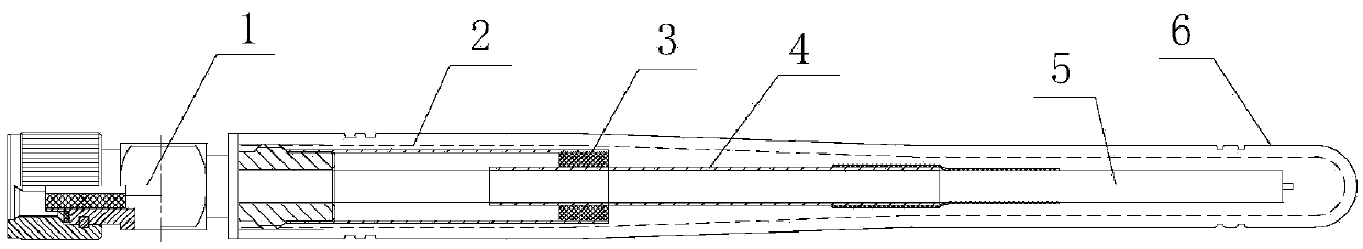
[0013] The present invention will be further described now in conjunction with accompanying drawing. These drawings are simplified schematic diagrams only to illustrate the basic structure of the present invention in a schematic way, so they only show the components relevant to the present invention.

[0014] As shown in Figure 1, a kind of LTE antenna comprises a coaxial connector 1, a first copper pipe 2, a second copper pipe 4 and an electronic wire 5, and the coaxial connector 1 is a radio frequency coaxial connector 1; the first One end of the copper tube 2 is connected to the coaxial connector 1, the other end of the first copper tube 2 is connected to one end of the second copper tube 4, the other end of the second copper tube 4 is connected to the electronic wire 5, and the electronic wire 5 passes through the first The second copper pipe 4 and the first copper pipe 2 are connected to the coaxial connector 1 .

[0015] The coaxial connector 1 is also connected with a ...


PUM


Abstract

The invention relates to an LTE antenna comprising a coaxial connector, a first copper tube, a second copper tube and an electronic wire. One end of the first copper tube is connected with the coaxial connector, and the other end of the first copper tube is connected with one end of the second copper tube. The other end of the second copper tube is connected with the electronic wire. The electronic wire penetrates through the second copper tube and the first copper tube to be connected with the coaxial connector. Labor cost and purchase cost are greatly reduced on the basis of guaranteeing antenna performance.

Description

technical field [0001] The invention relates to the field of wireless communication, in particular to an LTE antenna. Background technique [0002] Conventional antennas with external LTE antennas are large in size, costly to purchase raw materials, and consume man-hours. Contents of the invention [0003] The technical problem to be solved by the present invention is to provide an LTE antenna by overcoming the deficiencies of the prior art. [0004] The technical solution adopted by the present invention to solve the technical problem is: a kind of LTE antenna, comprising a coaxial connector, a first copper tube, a second copper tube and an electronic wire, one end of the first copper tube is connected to the coaxial connector connection, the other end of the first copper tube is connected to one end of the second copper tube, the other end of the second copper tube is connected to an electronic wire, and the electronic wire passes through the second copper tube and the ...

Claims


Application Information

Patent Timeline
Patent Type & Authority Applications(China)
IPC IPC(8): H01Q1/50
CPCH01Q1/50
Inventor 不公告发明人
Owner ZHANGJIAGANG ZHONGNAN ELECTRONICS
Why Eureka
Try Eureka