A thread-free connection structure and layout of an air compressor exhaust pipe

An air compressor and connection structure technology, applied in the field of compressors, can solve the problems of insufficient flexibility in the layout of the compressor exhaust system, increase the number of processing procedures and installation procedures, and reduce the reliability of the entire compressor, so as to avoid Tighten the operating space of the installation wrench, improve the reliability of the whole machine, reduce the number of parts and the effect of the manufacturing process and the installation process

Active Publication Date: 2019-02-05
ZHEJIANG HONGYOU AIR COMPRESSOR MFG
View PDF18 Cites 0 Cited by
  • Summary
  • Abstract
  • Description
  • Claims
  • Application Information

AI Technical Summary

Problems solved by technology

Obviously, the connection structure and layout scheme of the above-mentioned traditional air compressor exhaust pipe 3 still have some areas to be improved: 1) The traditional structure adopts the structure of the pipe joint 2, the thread structure 2a and the lock nut 4, which can certainly be Reliably connecting the exhaust pipe 3 to the exhaust port 1a of the cylinder head 1, and the exhaust pipe 3 to the pipe-through valve 5 will inevitably increase the number of parts of the compressor, and will also increase more processing steps and The installation process, for example, requires at least one pipe joint 2 and two lock nuts 4, as well as the derived thread structure 2a machining process and installation in place process. Undoubtedly, the more parts and the more manufacturing and installation links, It will not only lead to an increase in the production cost of the compressor, but also a higher probability of failure, so it will definitely reduce the reliability of the compressor as a whole; 2) The traditional structure uses a pipe joint 2, a threaded structure 2a and a lock nut 4 It is necessary to consider the installation space, such as the wrench operating space necessary for tightening the thread. At this time, the fastening structure of each component needs to leave enough transitional space. For example, the pipe valve 5 cannot be too close to the gas storage tank 6, and the The joint 2 must keep a sufficient distance from the cylinder head 1, and the exhaust pipe 3 cannot be too close to the crankcase of the compressor, etc., which not only causes the layout of the compressor exhaust system to be inflexible, but also increases unnecessary redundant space and The length of the transition pipe increases the manufacturing materials of the compressor, resulting in an increase in the production cost of the compressor; 3) In the traditional structural layout, the exhaust pipe 3 must adopt a longer layout structure, because the main components in the pipe-through valve 5 are Rubber gaskets and preloaded springs, the biggest enemy of these components is high temperature. It is well known that the high-pressure exhaust of the compressor has a very high temperature. In order to prevent the rubber gaskets and preloaded springs from working at higher temperatures, the traditional method It is to lengthen the length of the exhaust pipe 3 to dissipate heat, and at the same time keep the pipe-through valve 5 away from the exhaust chamber of the compressor, and lay cooling fins 3a on the outer surface of the exhaust pipe 3 to enhance heat dissipation. In order to minimize the heat transferred to the pipe-through valve 5, it is obvious that these two measures will inevitably increase the production cost of the compressor due to the increase of materials; 4) The exhaust pipe 3 in the traditional structure adopts an exposed cooling layout structure, the main reason is that the length of the exhaust pipe 3 is too long, and the cost of completely covering it and implementing the forced cooling of the air guide type is too high, so the existing technology almost uses the exposed method to rely on the outside air. Natural cooling, the cooling effect is obviously unsatisfactory, the resulting disadvantage is that the operating temperature of the main components in the pipe-through valve 5 is still high, which is also a reason for the low reliability of the current air compressor. In addition, the exposed layout Exhaust pipe 3 also has the potential safety hazard of scalding people and animals

Method used


Image

  • A thread-free connection structure and layout of an air compressor exhaust pipe
  • A thread-free connection structure and layout of an air compressor exhaust pipe
  • A thread-free connection structure and layout of an air compressor exhaust pipe

Examples


Embodiment Construction

[0033] The present invention will be further described below with specific embodiment, see figure 1 -14:

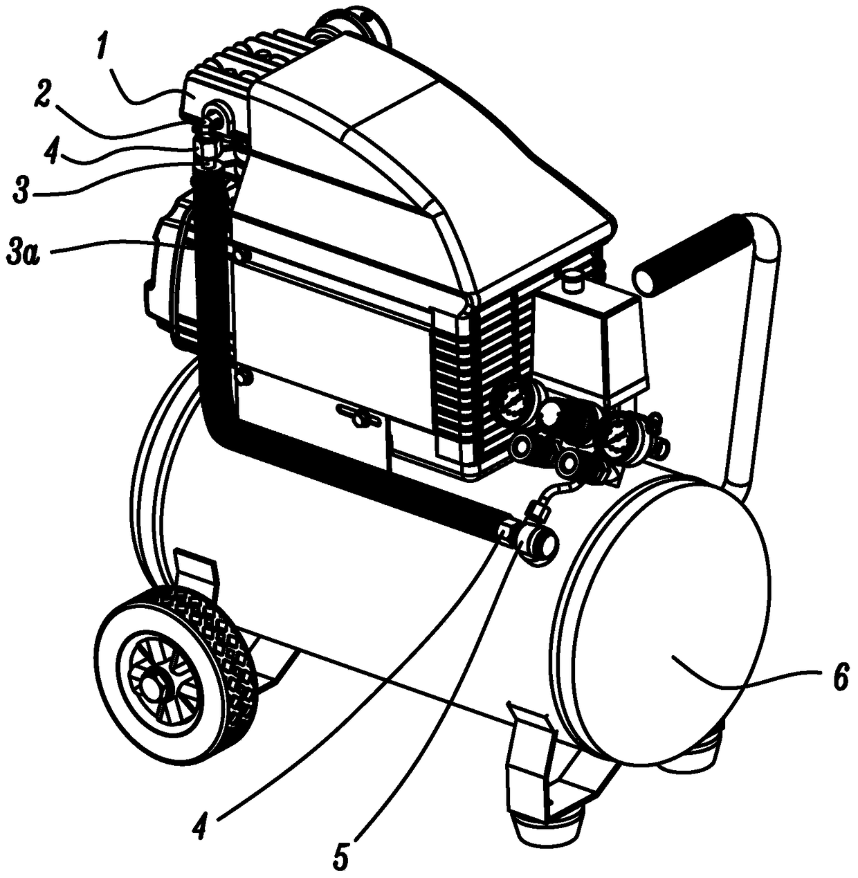
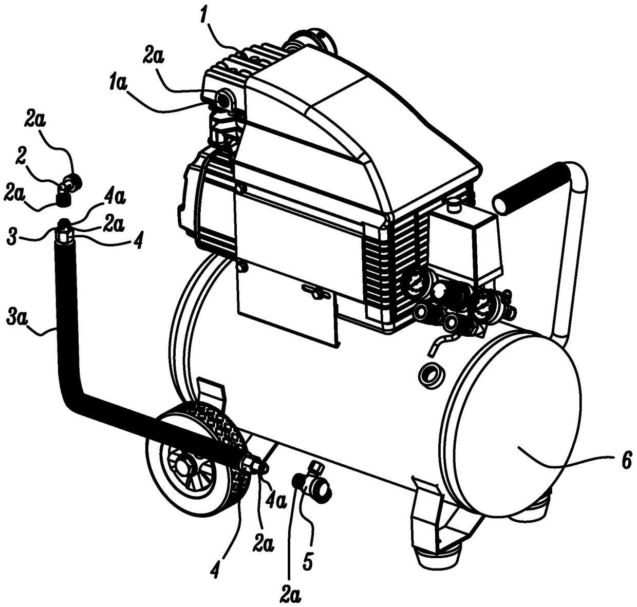
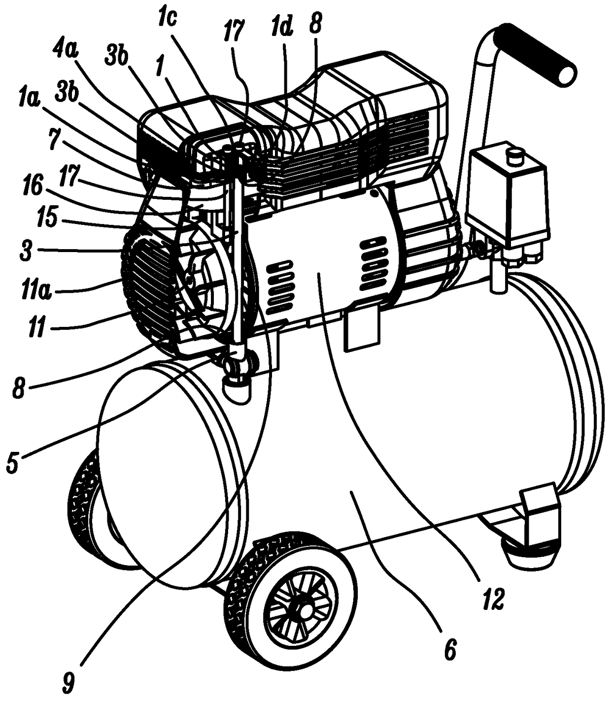
[0034] A thread-free connection structure and layout of an air compressor exhaust pipe, including a cylinder head 1, an exhaust chamber 1b, a valve seat plate 7, and an exhaust port 1a set on the cylinder head 1 or / and valve seat plate 7 , exhaust pipe 3, pipe-through valve 5 and gas storage tank 6, wherein the exhaust port 1a communicates with the exhaust chamber 1b through the exhaust passage 1c, and the pipe-through valve 5 and the gas storage tank 6 can be directly connected or indirectly Connection (when it is an indirect connection, a section of transition pipeline or other components can be added between the pipe valve 5 and the gas storage tank 6), and the components that can control the conduction or cut-off of the gas path can be set in the pipe valve 5 (not shown in the figure), in addition, the valve seat plate 7 is used to arrange various air valves of the c...


PUM


Abstract

Provided is a connection structure for an air compressor exhaust pipe, and arrangement thereof, comprising an air cylinder cover (1), an exhaust chamber (1b), a valve seat plate (7), an exhaust vent (1a) disposed on the air cylinder cover (1) and / or the valve seat plate (7), an exhaust pipe (3), a pipe communication valve (5), and an air storage tank (6); one end of the exhaust pipe (3) is connected to the exhaust vent (1a), and the other end of the exhaust pipe (3) is connected to the pipe communication valve (5); furthermore, at least one of the connections of the two connections between the exhaust pipe (3) and the exhaust vent (1a) and between the exhaust pipe (3) and the pipe communication valve (5) is an insertable threadless connection structure. The structure abandons the threaded mount of a conventional compressor exhaust pipe, reducing production costs and improving the operational reliability of the present compressor.

Description

technical field [0001] The invention belongs to the technical field of compressors, and relates to a connection structure and a layout scheme of an air compressor exhaust pipe, in particular to an exhaust pipe that connects a compressor cylinder head exhaust chamber with an air storage tank The connection structure and its layout scheme, more specifically relate to a structure and its layout scheme of an air compressor exhaust pipe with a thread-free connection. Background technique [0002] The air compressor always needs to guide the high-pressure air it outputs to the air storage tank for storage in case of emergency. The working method of the reciprocating piston compressor is to compress the low-pressure air through the piston to increase the pressure. When the pressure reaches the set value, it enters the exhaust chamber of the cylinder head through the exhaust check valve, and then is exhausted by a The pipe is delivered to the air storage tank for use. figure 1 wit...

Claims


Application Information

Patent Timeline
Patent Type & Authority Patents(China)
IPC IPC(8): F04B39/12F04B39/10F04B41/02F04B39/06
CPCF04B39/10F04B39/12F04B41/02
Inventor 耿爱农陈威龙阮勤江陈君立
Owner ZHEJIANG HONGYOU AIR COMPRESSOR MFG
Why Eureka
Try Eureka