
Cantilever type longitudinal axis digging and anchoring machine and step-by-step construction stage coal tunnel forming construction process

A cantilever type, bolt-digger technology, applied in cutting machinery, earth-moving drilling, etc., can solve problems such as affecting construction efficiency and construction speed, roof easily falling off, and tension in coal mining, so as to improve construction efficiency and construction speed. , The effect of preventing roof fall and improving the utilization rate of working hours

Inactive Publication Date: 2016-03-02
内蒙古维维能源有限公司
View PDF8 Cites 3 Cited by
  • Summary
  • Abstract
  • Description
  • Claims
  • Application Information

AI Technical Summary

Problems solved by technology

[0002] The roof (coal) of many coal mines and roadways is prone to roof fall during the excavation process. In order to prevent roof fall during the excavation construction process, the construction can only be carried out with a small cycle footage; The operation requires frequent switching between the two processes of excavation and anchoring, which seriously affects the construction efficiency and construction speed. This is why the monthly footage of many fully mechanized excavation working faces is less than 400m, and some even less than 300m. The main reason
This kind of construction speed not only affects the economic benefits of the enterprise, but also causes tension in the mining relationship of the coal mine, and even affects the continuity of the working face of the coal mine.

Method used


Image

  • Cantilever type longitudinal axis digging and anchoring machine and step-by-step construction stage coal tunnel forming construction process
  • Cantilever type longitudinal axis digging and anchoring machine and step-by-step construction stage coal tunnel forming construction process
  • Cantilever type longitudinal axis digging and anchoring machine and step-by-step construction stage coal tunnel forming construction process

Examples


no. 1 example

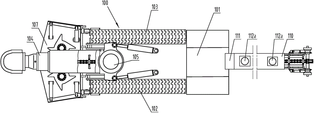
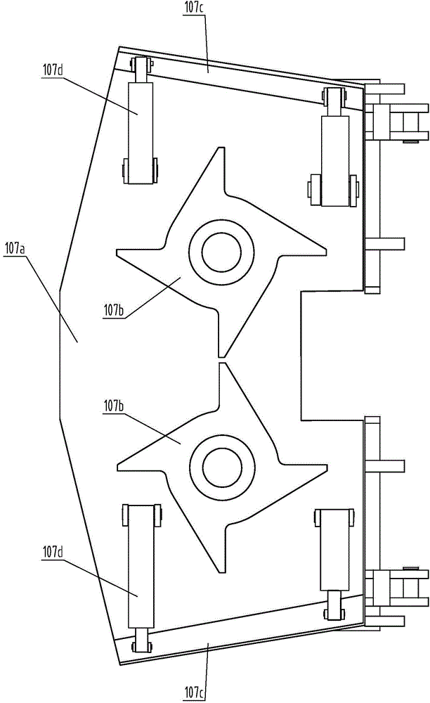
[0043] Depend on figure 1 and figure 2 It can be seen that the cantilever type longitudinal axis bolter includes: a cantilever type longitudinal axis roadheader 100, the cantilever type longitudinal axis roadheader 100 includes a frame body 101, a left walking part 102, a right walking part 103, a cutting part 104, a rotary Body 105, rear support body 106, loading mechanism 107, first scraper conveyor 108, electric control system, hydraulic system, spraying system and cooling system; first scraper conveyor 108 includes a tail part arranged on the frame body 101 109, protruding out from the machine head part 110 in the horizontal direction at the rear of the frame body 101, between the machine head part 110 and the tail part 109 is connected with an inclined slope chute 111, on the machine head part 110 is provided with several An airborne rock bolter 112a.

[0044] During use, because the first scraper conveyor 108 is stretched out on the head portion 110 of the frame body ...

no. 2 example

[0050] Depend on Figure 4 It can be seen that this embodiment is basically the same as the first embodiment, the differences are:

[0051] The first scraper conveyor 108 is provided with an elevating work platform that supports workers to facilitate their work. Of course, the elevating work platform can also be arranged between the airborne bolter rig 112a and the head part 110 as required. The platform includes a platform 114, between the platform 114 and the head part 110, a first frame body 115 and a second frame body 116 connected in the middle are provided, the top of the first frame body 115 is hingedly connected with a side part of the platform 114, and the first The bottom end of the frame body 115 is slidably connected with the head part 110, the top of the second frame body 116 is slidably connected with the other side of the platform 114, and the bottom end of the second frame body 116 is hingedly connected with the head part 110. A hydraulic lift cylinder 117 is ...

no. 3 example

[0053] Depend on Figure 5 , Figure 6 and Figure 7 It can be seen that this embodiment is basically the same as the first embodiment, the differences are:

[0054] The cantilever type longitudinal axis bolter also includes a second scraper conveyor 113, the tail end of the second scraper conveyor 113 is located below and overlaps the nose portion 110 of the first scraper conveyor 108, and the second scraper conveyor 113 The head end of the machine is overlapped with the external supporting transportation equipment; several airborne bolters 112b are arranged on the second scraper conveyor 113, and in order to facilitate the movement of the second scraper conveyor 113 on the left and right sides of the second scraper conveyor 113 The left crawler traveling mechanism 118a and the right crawler traveling mechanism 118b are respectively provided on the top; in order to enhance the safety performance, avoid the second scraper conveyor 113 from colliding with the cantilever type ...


PUM


Abstract

The present invention belongs to the technical field of coal mine coal tunnel digging construction equipment, and particularly relates to a cantilever type longitudinal axis digging and anchoring machine, which comprises a rack body, a left walking part, a right walking part, a cutting part, a rotation body, a rear support body, a loading mechanism, a first scraping plate conveyor, an electric control system, a hydraulic system, a spraying system and a cooling system, wherein the first scraping plate conveyor comprises a machine tail portion arranged on the rack body and a machine head portion extending out of the rack body rear portion, and the machine head portion is provided with a plurality of airborne anchor rod drillers. According to the present invention, during the use, when the cantilever type longitudinal axis digging and anchoring machine digs, the coal tunnel is subjected to anchoring fixation support by using the airborne anchor rod drillers, such that the parallel operations of digging and anchoring can be achieved, the time consumption problem caused by the frequent switching between the two processes such as digging and anchoring can be solved, the construction efficiency and the construction speed can be improved, and the puking phenomenon can be prevented.

Description

technical field [0001] The invention belongs to the technical field of coal mine roadway excavation construction equipment, and in particular relates to a cantilever type longitudinal axis bolter and a coal roadway construction technology in the step-by-step construction stage. Background technique [0002] The roof (coal) of many coal mines and roadways is prone to roof fall during the excavation process. In order to prevent roof fall during the excavation construction process, the construction can only be carried out with a small cycle footage; The operation requires frequent switching between the two processes of excavation and anchoring, which seriously affects the construction efficiency and construction speed. This is why the monthly footage of many fully mechanized excavation working faces is less than 400m, and some even less than 300m. the main reason. This kind of construction speed not only affects the economic benefits of the enterprise, but also causes tension ...

Claims


Application Information

Patent Timeline
IPC IPC(8): E21C25/06
Inventor 曲天智
Owner 内蒙古维维能源有限公司
Learn More