
Pole foundation pitting rope wear, application thereof and pole foundation pitting method

A technology of pole and tower foundation and ropes, which is applied in the direction of foundation structure engineering, foundation structure test, construction, etc. The problem of high cost can reduce the cost of surveying and mapping, save manpower and material resources, and achieve the effect of high surveying and mapping efficiency.

Active Publication Date: 2016-03-02
STATE GRID CORP OF CHINA +2
View PDF6 Cites 2 Cited by
  • Summary
  • Abstract
  • Description
  • Claims
  • Application Information

AI Technical Summary

Problems solved by technology

Therefore, the measurement of this type of tower foundation sub-pit is a repeated measurement operation at different locations, which is limited by the skills and operating practices of the surveyors, resulting in low efficiency and high surveying and mapping costs
[0004] At the same time, after the location measurement of the sub-pit is completed, it is difficult for the construction party and the supervisor to check and review the correctness of the location and direction of the sub-pit, foundation columns and foot bolts during and after the construction of the pole tower. There is no on-site verification available in the prior art tool

Method used


Image

  • Pole foundation pitting rope wear, application thereof and pole foundation pitting method
  • Pole foundation pitting rope wear, application thereof and pole foundation pitting method
  • Pole foundation pitting rope wear, application thereof and pole foundation pitting method

Examples


specific Embodiment approach 1

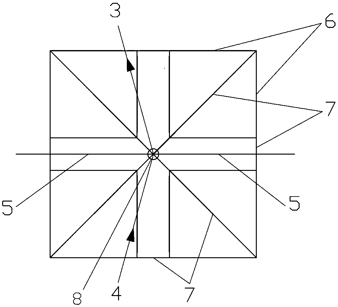
[0030] A kind of rope tool for pole and tower foundation pit division, which is a rope net formed by fixed connection of positioning wire rope, pit contour wire rope 6 and connecting wire rope 7, said positioning wire rope is provided with rope tool positioning point 8, so The positioning wire rope is an angle bisector wire rope 5, and the positioning wire rope is fixedly connected to the connecting wire rope 7, and is fixed in the rope net by the connecting wire rope 7, and it is a straight line after being unfolded; the pit position contour wire rope 6 There are several groups, which are divided into several groups. The number of groups is the same as the number of foundation pits that have been determined. In the same group, the contour lines 6 of each pit position are fixed and connected in turn to form a closed figure. The pit mouth contour figure, the pit position contour line rope 6 of each group is fixedly connected to the connection line 7, and is fixed in the rope net...

Embodiment 1

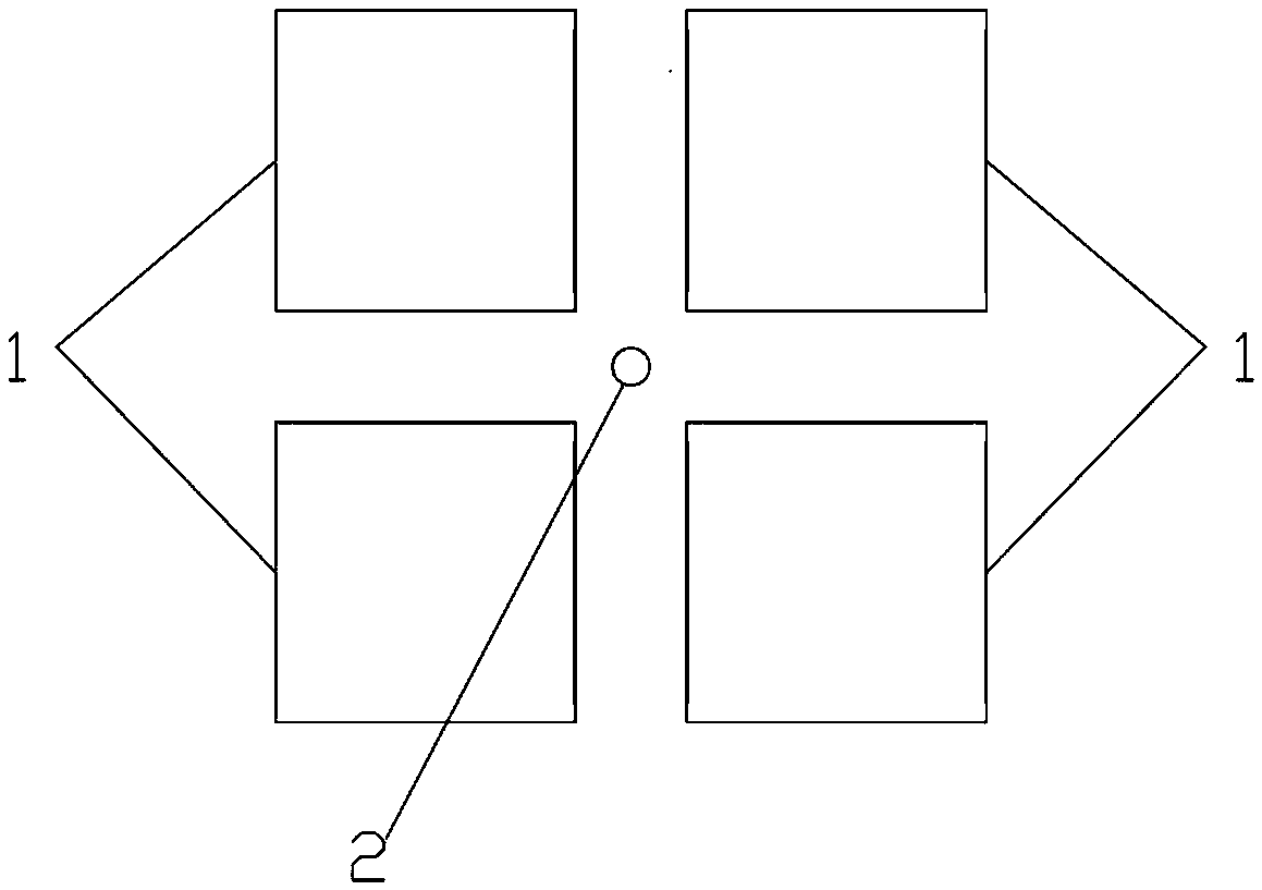
[0038] A kind of pit-dividing rope for tower foundation, see figure 2 , the foundation pit of the tower is as follows figure 1 As shown in the rectangle, there are 16 pit contour lines 6, each set of four, and the first position is fixedly connected to form a closed figure, and it becomes a rectangle after unfolding; there are 6 connecting lines 7, of which 2 are connecting lines 7 It is a diagonal connecting line, and the diagonal connecting line passes through the anchor point 8 of the rope and is fixedly connected to the two sets of pit contour lines 6 in the diagonal direction, and the two sets of pit contour lines in the diagonal direction The near apex of the rectangle formed by the rope 6 near the anchor point 8 of the rope and the far apex away from the anchor point 8 of the rope are all fixedly connected on the diagonal connecting wires in the diagonal direction; the other four connecting wires 7 It is a side connecting wire rope, which is fixedly connected to the o...

specific Embodiment approach 2

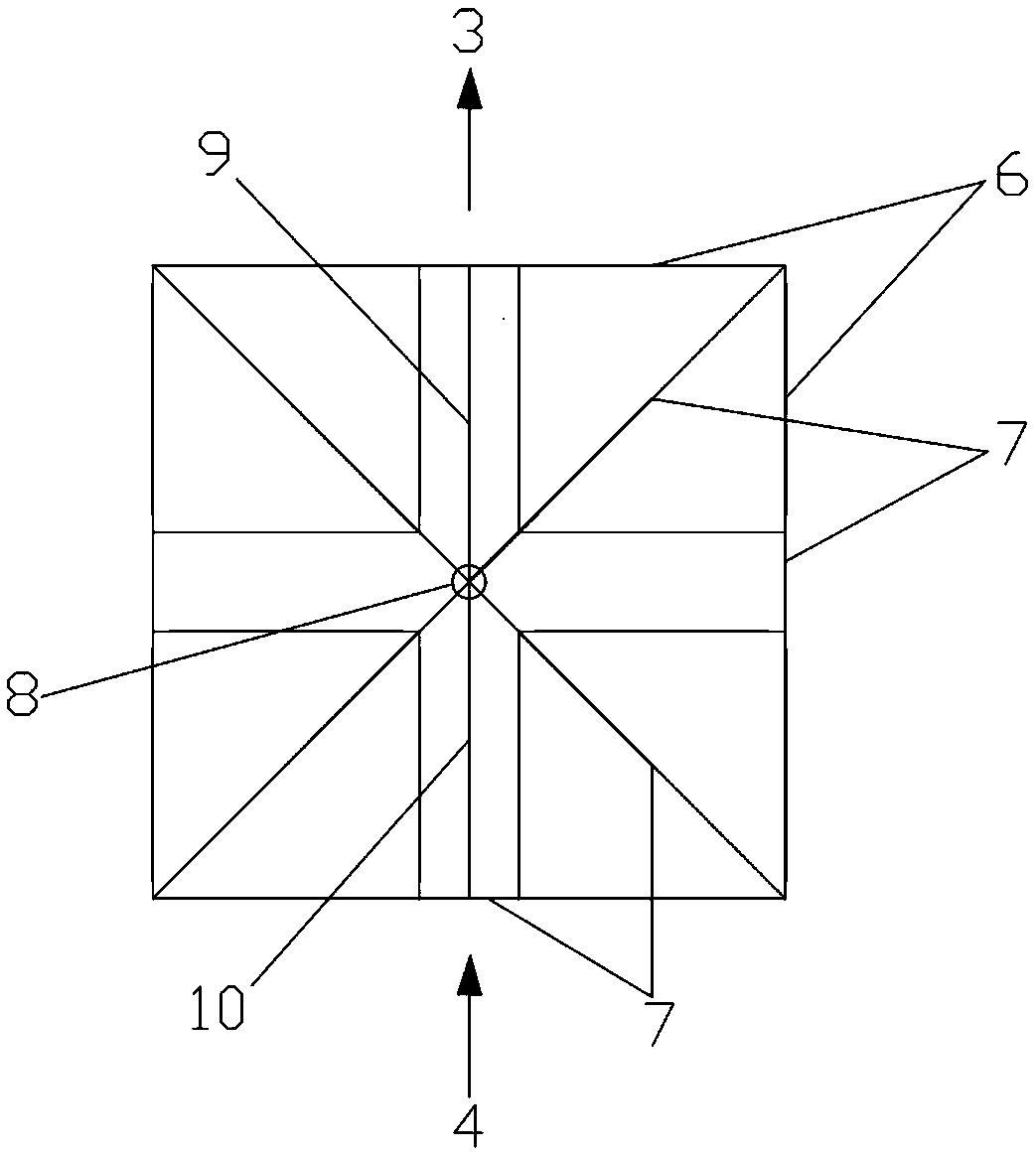
[0040] A kind of straight pole tower foundation pit-dividing rope, see image 3 , the power receiving side direction 4 and the power transmitting side direction 3 of the straight pole tower are located on the same straight line, and the rope is a rope net formed by fixedly connecting the positioning wire rope, the pit contour wire rope 6 and the connecting wire rope 7 , the positioning wire rope is the power transmission side direction wire rope 9 or the power receiving side direction wire rope 10, the positioning wire rope is provided with a rope positioning point 8, and the positioning wire rope is fixedly connected to the connection wire rope 7, by The connecting wire rope 7 is fixed in the rope net, and it is a straight line after it is unfolded; the pit position outline wire rope 6 is multiple, and is divided into several groups, and its grouping number is the same as the foundation pit number of the sub-pit that has been determined. Each pit outline line rope 6 is fixedl...


PUM


Abstract

The invention relates to the technical field of construction measurement of power transmission and transformation engineering projects, particularly discloses a pole foundation pitting rope wear, application thereof and a pole foundation pitting method. The rope wear is a rope net formed by enabling a positioning line rope, pit position contour line ropes and connecting line ropes to be fixedly connected. In accordance with pole foundations which are the same in the size of a pit mouth and the foundation foot distance of the pit, a pole center, an angular bisector, a foundation pit mouth profile graph and the relative positions of the pole center, the angular bisector and the foundation pit mouth profile graph are recorded in the graphical rope wear through various line ropes; the visualization and repeatability of the rope wear are utilized, the rope wear is placed on a pole foundation pitting floor to be measured; after the rope wear , and the angular bisector and the pole center of the pole foundation to be measured are positioned, the foundation pit showed in the rope wear is the foundation pit of the pole foundation pit to be measured; labeling is realized on the ground with a mark, so that pitting measurement is realized. Through the adoption of the pole foundation pitting rope wear disclosed by the invention, the tower foundation pit can be quickly and conveniently determined or checked, the working efficiency is improved, time and manpower which are consumed for measurement are reduced, and the measurement cost is reduced. The pole foundation pitting rope wear has the advantages of being simple in structure and convenient to manufacture and use.

Description

technical field [0001] The invention relates to the technical field of construction measurement of power transmission and transformation projects, in particular to the technical field of pole tower sub-pit measurement. Background technique [0002] In the construction process of power system transmission and transformation line engineering, the foundation of the tower is the most important thing in the construction. It is very important to accurately locate the location of the sub-pit and the position of the foundation column and foot bolt in the sub-pit, so it is very important for the surveyors. Professional skill requirements, especially for complex foundations, are more professional and technical. In the prior art pit division method, technicians use a theodolite or a total station to divide the line pole and tower, which takes 40-60 minutes or even longer, and requires 4-6 personnel. Returning in vain, it is difficult to find the location of the sub-pit, the efficiency...

Claims


Application Information

Patent Timeline
Patent Type & Authority Applications(China)
IPC IPC(8): E02D33/00
CPCE02D33/00
Inventor 薛勇伟
Owner STATE GRID CORP OF CHINA
Learn More