
Horizontal-type unilateral circle-curling die for thin plate

A technology for rolling round dies and thin plates, which is applied in the field of horizontal thin plate single-side rolling round dies, which can solve problems such as production difficulties, failure to meet product quality and batch production requirements, and high scrap rate

Inactive Publication Date: 2016-03-02
CHONGQING YANJI SCI & TECH CO LTD
View PDF0 Cites 2 Cited by
  • Summary
  • Abstract
  • Description
  • Claims
  • Application Information

AI Technical Summary

Problems solved by technology

[0002] Hinge parts are suitable for non-load-bearing hinges for the flexible connection of the cover and the plate. They are mainly used in the fields of aviation, aerospace, and ships. Because they are used for the flexible connection of the cover and the plate, the structural shape and size of the parts are required. Strict, the material is 2A12-O (LY12-M), 30CrMnSiA, the thickness is 0.5, 0.8, 1.0, 1.2, 1.5, and there are many specifications. There should be no depressions, scratches, burrs and other mechanical damage on the surface of the parts. For Hinge (hinge) parts, according to the current relevant information, usually the head of the blank is pre-bent before being rolled into a circle. Due to the thin material, the part is easy to lose stability when it is bent and rolled, and the quality of the bent part is poor. The size and roundness are not easy to control, the scrap rate is high, and even the bending and rounding fail, the production is difficult, it cannot be formed, and it cannot meet and adapt to product quality and batch production requirements.
Moreover, the friction between the blank and the mold cavity surface is relatively large during molding, which is likely to cause wear and scratches on the mold cavity, which affects the quality and size requirements of the workpiece.

Method used


Image

  • Horizontal-type unilateral circle-curling die for thin plate

Examples


Embodiment Construction

[0010] The present invention will be described in further detail below by means of specific embodiments:

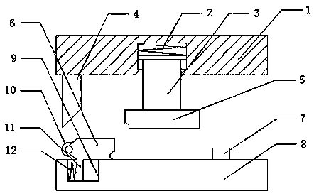
[0011] The reference signs in the drawings of the specification include: upper die base 1, compression spring 2, pressure block 3, ejector rod 4, pressure head 5, slider 6, stop block 7, lower die base 8, chute 9, roller 10 , Push pedal 11, extension spring 12.

[0012] The embodiment is basically as attached figure 1 Shown: a horizontal thin plate unilateral rolling die, including an upper mold base 1, a lower mold base 8, and a pressing block 3. The middle part of the lower end of the upper mold base 1 is depressed upward to form a groove, and the opening of the groove faces The inner contraction forms a limit ring, the upper part of the pressure block 3 is located in the groove, the lower end of the pressure block 3 extends circumferentially to form a pressure head 5, and the top end of the pressure block 3 extends circumferentially to form a limit platform. The bit ...


PUM


Abstract

The invention discloses a horizontal-type unilateral circle-curling die for a thin plate, and belongs to the field of dies. The horizontal-type unilateral circle-curling die for the thin plate comprises an upper die base, a lower die base and a pressing block. The pressing block is connected to the lower end of the upper die base in a sliding mode. The lower end of the pressing block extends to form a pressing head in the circumferential direction. A pressing spring is fixed between the top end of the pressing block and the upper die base. An ejection rod is arranged in the position, on one side of the pressing block, of the upper die base. An inclined wedge inclining towards the pressing block is arranged at the lower end of the ejection rod. A first arc-shaped forming groove is formed in the side, close to the inclined wedge, of the lower end of the pressing head. The lower die base is provided with a sliding groove, a sliding block and a check block. The check block and the sliding block are oppositely located on the two sides of the pressing head respectively. A second arc-shaped forming groove with the same arc radius as the first forming groove is formed in the end, close to the check block, of the sliding block. The top of the second forming groove is flush with the top of the first forming groove. A rolling wheel is fixed to the end, close to the inclined wedge, of the sliding block and is located below the inclined wedge. According to the scheme, a workpiece is smoother and not prone to deformation in the circle-curling process, the condition of workpiece instability is rare in the machining process, and the anti-instability effect on thin and long plates is especially significant.

Description

technical field [0001] The invention relates to the field of moulds, in particular to a horizontal thin-plate single-side rolling round die. Background technique [0002] Hinge parts are suitable for non-load-bearing hinges for the flexible connection of the cover and the plate. They are mainly used in the fields of aviation, aerospace, and ships. Because they are used for the flexible connection of the cover and the plate, the structural shape and size of the parts are required. Strict, the material is 2A12-O (LY12-M), 30CrMnSiA, the thickness is 0.5, 0.8, 1.0, 1.2, 1.5, and there are many specifications. There should be no depressions, scratches, burrs and other mechanical damage on the surface of the parts. For Hinge (hinge) parts, according to the current relevant information, usually the head of the blank is pre-bent before being rolled into a circle. Due to the thin material, the part is easy to lose stability when it is bent and rolled, and the quality of the bent par...

Claims


Application Information

Patent Timeline
IPC IPC(8): B21D37/10B21D5/06
CPCB21D37/10B21D5/06
Inventor 李良燕
Owner CHONGQING YANJI SCI & TECH CO LTD
Learn More