Method for producing plated laminate, and plated laminate
A manufacturing method and laminated body technology, applied in contact manufacturing, contact parts, etc., can solve problems such as insufficient adhesion between tin plating and silver plating, and achieve excellent wear resistance, electrical conductivity and fit , Inhibition of embrittlement, excellent wear resistance
- Summary
- Abstract
- Description
- Claims
- Application Information
AI Technical Summary
Problems solved by technology
Method used
Image
Examples
no. 1 approach
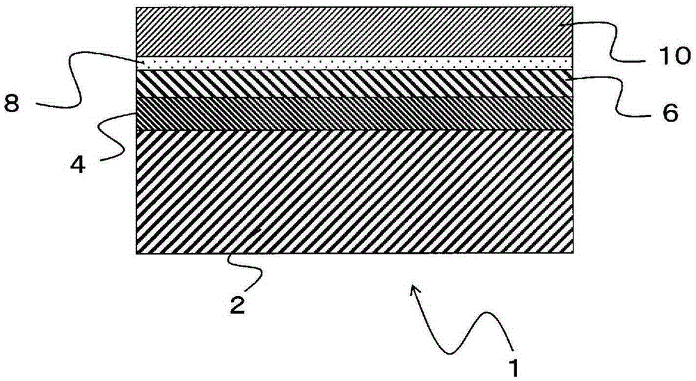
[0129] figure 2 It is a schematic sectional view of 1st Embodiment of the plated laminated body of this invention. In the plated laminate 1 , the tin-plated layer 4 is formed on the surface of the metal substrate 2 , and the nickel-plated layer 6 is formed on the entire surface of the tin-plated layer 4 . In addition, a silver strike plating layer 8 is formed on the entire surface of the nickel plating layer 6 , and a silver plating layer 10 is formed on the entire surface of the silver strike plating layer 8 . In addition, a silver strike plating layer (not shown) similar to the silver strike plating layer 8 is formed between the tin plating layer 4 and the nickel plating layer 6 as needed.
[0130] The metal of the metal substrate 2 is not particularly limited as long as it has electrical conductivity. For example, aluminum and aluminum alloys, iron and iron alloys, titanium and titanium alloys, stainless steel, copper and copper alloys, etc. can be mentioned. Among them, ...
no. 2 approach
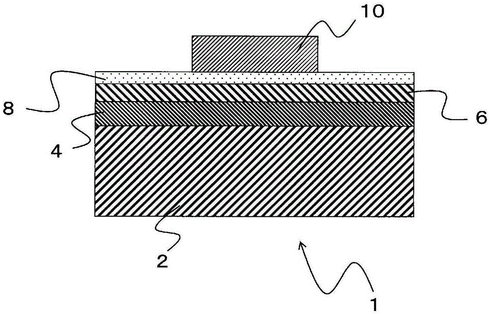
[0136] image 3 It is a schematic sectional view of 2nd Embodiment of the plated laminated body of this invention. In the plated laminate 1 , the tin-plated layer 4 is formed on the surface of the metal substrate 2 , and the nickel-plated layer 6 is formed on the entire surface of the tin-plated layer 4 . In addition, a silver strike plating layer 8 is formed on the entire surface of the nickel plating layer 6 , and a silver plating layer 10 is formed on a part of the surface of the silver strike plating layer 8 . In addition, except that the silver plating layer 10 is formed on a part of the silver strike plating layer 8, it is the same as the first embodiment.
no. 3 approach
[0138] Figure 4 It is a schematic sectional view of 3rd Embodiment of the plated laminated body of this invention. In the plated laminate 1 , the tin-plated layer 4 is formed on the surface of the metal substrate 2 , and the nickel-plated layer 6 is formed on a part of the surface of the tin-plated layer 4 . In addition, a silver strike plating layer 8 is formed on the entire surface of the nickel plating layer 6 , and a silver plating layer 10 is formed on the entire surface of the silver strike plating layer 8 . In addition, a nickel plating layer 6 is formed on a part of the surface of the tin plating layer 4, a silver strike plating layer 8 is formed on the entire surface of the nickel plating layer 6, and a silver plating layer is formed on the entire surface of the silver strike plating layer 8. 10. Other than that, it is the same as the first embodiment.
PUM
| Property | Measurement | Unit |
|---|---|---|
| thickness | aaaaa | aaaaa |
| thickness | aaaaa | aaaaa |
| Vickers hardness | aaaaa | aaaaa |
Abstract
Description
Claims
Application Information
 - R&D Engineer
- R&D Manager
- IP Professional
- Industry Leading Data Capabilities
- Powerful AI technology
- Patent DNA Extraction
Browse by: Latest US Patents, China's latest patents, Technical Efficacy Thesaurus, Application Domain, Technology Topic, Popular Technical Reports.
© 2024 PatSnap. All rights reserved.Legal|Privacy policy|Modern Slavery Act Transparency Statement|Sitemap|About US| Contact US: help@patsnap.com


