A display product frame and its production process
A display product and production process technology, applied in the field of display product frame and its production process, can solve the problems of easy occurrence of defective products, high processing cost, long assembly time, etc., and achieve the effect of a reasonable and simple frame structure
- Summary
- Abstract
- Description
- Claims
- Application Information
AI Technical Summary
Problems solved by technology
Method used
Image
Examples
Embodiment 1
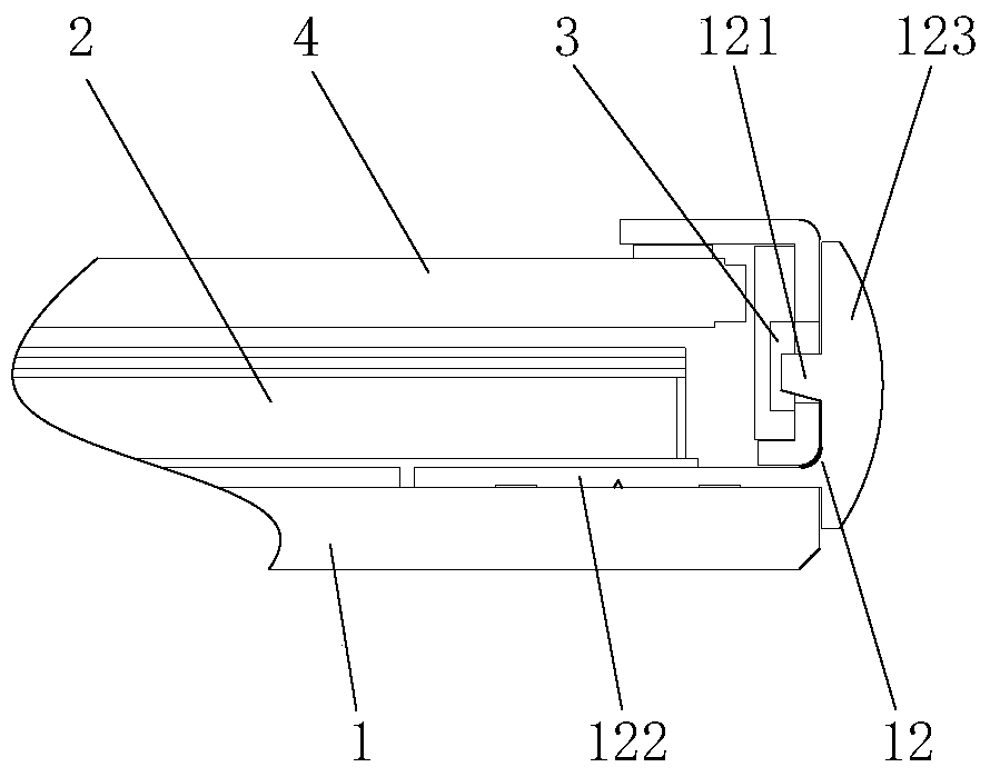
[0037] The present invention provides a display product frame, such as figure 1 As shown, it includes a backplane assembly 1 and a fixed frame 3. The backlight module 2 of the display product is fixed on the backplane assembly 1. A display screen 4 is arranged above the backlight module 2. The fixed frame 3 and the backplane assembly 1 snap together, and fix the display screen 4 . The present invention can make the structure of the frame more reasonable and simple by fastening the fixed frame 3 and the back panel assembly 1 , and is narrower than the existing frame, satisfying people's demand for a narrow frame, and realizing the concept of an ultra-narrow frame.
[0038] refer to figure 2 , the backplane assembly 1 of this embodiment includes a backplane 11. Specifically, the backplane 11 is made of glass material. Compared with the existing metal material or plastic material, the backplane 11 made of glass material has high flatness. , so that the overall structure of the...
Embodiment 2
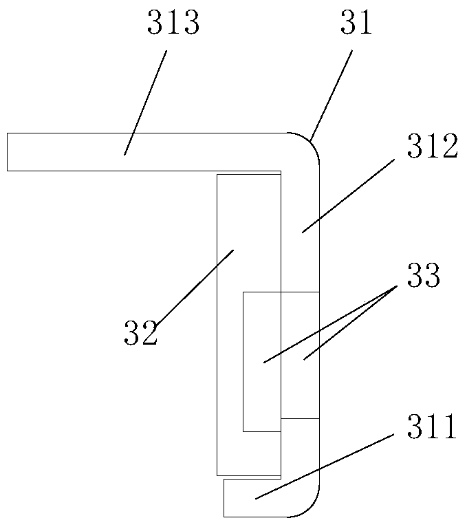
[0049] The difference between this embodiment and Embodiment 1 is that the structure of the fixed frame 3 and the connection method between the fixed frame 3 and the backplane assembly 1 are different, and the rest of the structure is the same as that of Embodiment 1, so only the structure of the fixed frame 3 and the fixing method are discussed here. The connection method between frame 3 and backplane assembly 1 is described as follows:
[0050] refer to Figure 4-6, the fixed frame 3 includes a middle frame 3a, specifically, the middle frame 3a includes a middle frame side plate 3a1, a middle frame horizontal plate 3a2, and a middle frame clamping plate 3a3, wherein the middle frame horizontal plate 3a2 and the middle frame clamping plate 3a3 A slot 3b is formed therebetween, and the buckle 121 is fastened to the slot 3b, so that the middle frame 3a is fixed to the profile reinforcement plate 12 of the back panel assembly 1 . In this embodiment, the backlight module 2 is lo...
Embodiment 3
[0054] The difference between this embodiment and Embodiment 1 and Embodiment 2 lies in the structure of the fixed frame 3, the connection method between the fixed frame 3 and the back panel assembly 1, and the structure of the profile reinforcement plate 12, and the rest of the structure is the same as that of Embodiment 1, so Here, only the structure of the fixed frame 3, the connection method between the fixed frame 3 and the back panel assembly 1, and the structure of the profile reinforcement plate 12 are explained:
[0055] refer to Figure 7-9 , the buckle 121 of the profile reinforcement plate 12 in this embodiment is provided on the long side 122 , which is used for connection with the fixed frame 3 .
[0056] Such as Figure 9 As shown, the fixed frame 3 includes a first middle frame 3A and a first front frame 3B, wherein the first middle frame 3A includes a first middle frame horizontal plate 3A1, a first middle frame clamping plate 3A2, a second middle frame The ...
PUM
 Abstract
Description
Claims
Application Information
 - R&D
- Intellectual Property
- Life Sciences
- Materials
- Tech Scout
- Unparalleled Data Quality
- Higher Quality Content
- 60% Fewer Hallucinations
Browse by: Latest US Patents, China's latest patents, Technical Efficacy Thesaurus, Application Domain, Technology Topic, Popular Technical Reports.
© 2025 PatSnap. All rights reserved.Legal|Privacy policy|Modern Slavery Act Transparency Statement|Sitemap|About US| Contact US: help@patsnap.com


