
Full-automatic edge gumming device of tentering and setting machine

A tenter and setting machine, a fully automatic technology, is applied in the processing of textile materials, the configuration of equipment for processing textile materials, textiles and papermaking, etc. Wrinkle and other problems, to achieve the effect of saving manpower, saving slurry, and avoiding omission of slurry coating

Active Publication Date: 2016-02-17
YOANTION IND INC LTD +1
View PDF7 Cites 3 Cited by
  • Summary
  • Abstract
  • Description
  • Claims
  • Application Information

AI Technical Summary

Problems solved by technology

At present, the cloth receiving method of the stenter setting machine generally adopts the rolling method, and the shaped cloth is rolled into cloth, but during the rolling process, the two ends of the cloth are prone to bulging, wrinkles and other bad defects due to the small binding force, and the In order to ensure that the selvedges at both ends of the cloth are neat and consistent, so that the two sides of the cloth are edged on the conveyor belt of the stenter setting machine between the windings. The existing edge treatment method is generally manual slurrying, that is, manually. The brush sticks the slurry to the two sides of the fabric, but manual slurrying is not only inefficient, but also prone to omissions, and the labor intensity of the staff is also high

Method used


Image

  • Full-automatic edge gumming device of tentering and setting machine
  • Full-automatic edge gumming device of tentering and setting machine
  • Full-automatic edge gumming device of tentering and setting machine

Examples


Embodiment

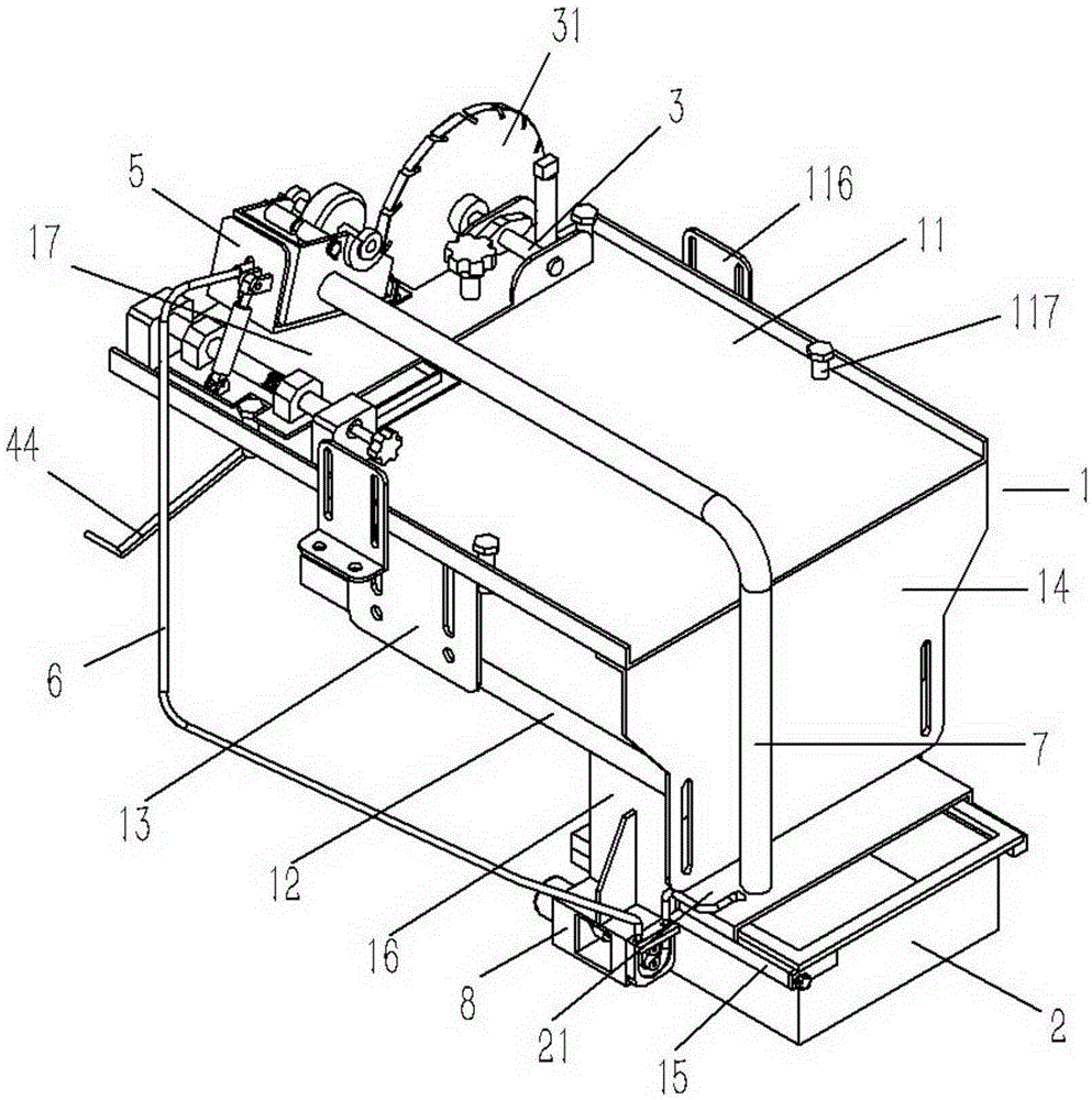
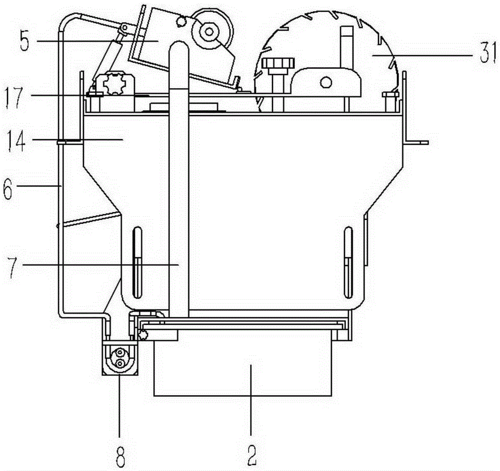
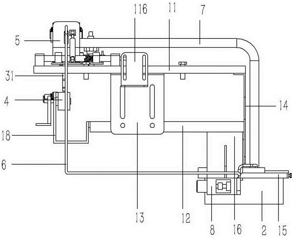
[0035] Example: see Figures 1 to 12 As shown, the fully automatic pulping device of the stenter setting machine includes installation brackets 1 fixed on both sides of the conveyor belt of the stenter setting machine. The installation bracket 1 is composed of an upper bracket plate 11 and a lower bracket plate 12. The upper bracket plate 11 The bottom surface is fixed with a vertical support plate 13, the lower end of the support plate 13 is fixed on the left and right sides of the lower support plate 12, the front side of the upper support plate 11 is fixed with a vertical baffle plate 14, the lower support plate 12 The front side of the baffle plate 14 is fixed, and the lower end of the baffle plate 14 is provided with a slurry basin 2, and the flanges on the left and right sides of the slurry basin 2 are placed on two support rods 15, and the support rods 15 are distributed on the baffle plate. The left and right sides of 14 are fixed on the connection plate 16, and the co...


PUM


Abstract

A full-automatic edge gumming device of a tentering and setting machine comprises an installation support fixed to the two sides of a conveyor belt of the tentering and setting machine. The installation support is composed of an upper support plate and lower support plates, wherein a vertical baffle is fixed to the front lateral side of the upper support plate, the front lateral sides of the lower support plates are fixed to the baffle, a sizing basin is arranged at the lower end of the baffle, flange edges on the left side and the right side of the sizing basin are arranged on two supporting rods, the supporting rods are distributed on the left side and the right side of the baffle and fixed to connection plates, and the connection plates are fixed to the left lateral side and the right lateral side of the lower support plates. A positioning plate is arranged on the upper end face of the rear side of the upper support plate. A supporting shaft is hinged to the right side of the positioning plate. One end of the supporting shaft extends out of the rear lateral side of the positioning plate to be fixedly connected to a pasting wheel. An auxiliary wheel is arranged under the pasting wheel and hinged to an auxiliary support. The auxiliary support is fixed to the rear lateral sides of the lower support plates. A sizing output mechanism is arranged on the portion, on the left side the pasting wheel, on the positioning plate. By means of the full-automatic edge gumming device, labor is saved, automatic edge gumming is achieved, and the work efficiency is improved.

Description

Technical field: [0001] The technical field of the stenter setting machine of the present invention, more specifically relates to the fully automatic paddle edge device and method of the stenter setting machine. Background technique: [0002] Stenter setting machine is a common textile equipment on the market at present, and it is mainly used in the tentering and setting of cloth. At present, the cloth receiving method of the stenter setting machine generally adopts the curling method, and the shaped cloth is rolled into cloth, but during the winding process, the two ends of the cloth are prone to bulging, wrinkles and other bad defects due to the small binding force, and the In order to ensure that the selvedges at both ends of the cloth are neat and consistent, so that the two sides of the cloth are edged on the conveyor belt of the stenter setting machine between winding and winding. The existing edge treatment method is generally manual slurrying, that is, manual use Th...

Claims


Application Information

Patent Timeline
Patent Type & Authority Applications(China)
IPC IPC(8): D06B1/14D06B23/20
CPCD06B1/14D06B23/20D06B2700/27
Inventor 陈少军
Owner YOANTION IND INC LTD
Learn More