Eureka AIR delivers breakthrough ideas for toughest innovation challenges, trusted by R&D personnel around the world.

Upender

A turning machine and frame technology, applied in the field of machinery, can solve the problems of breeding various pests, high labor intensity, bad environment, etc., and achieve the effect of reducing labor intensity, good effect, uniform and thorough turning

Inactive Publication Date: 2016-02-17
户尚伟
View PDF0 Cites 0 Cited by
  • Summary
  • Abstract
  • Description
  • Claims
  • Application Information

AI Technical Summary

Problems solved by technology

For example, if the pile of manure is not turned over in time (to facilitate exposure to sunlight and ventilation), it will easily produce odor due to internal fermentation, and at the same time, it will easily breed various pests; these will have a bad impact on the environment
[0003] At present, there is no appropriate machinery for material turning (manure turning), relying on manual material turning, labor-intensive and low efficiency

Method used


Image

  • Upender

Examples


Embodiment Construction

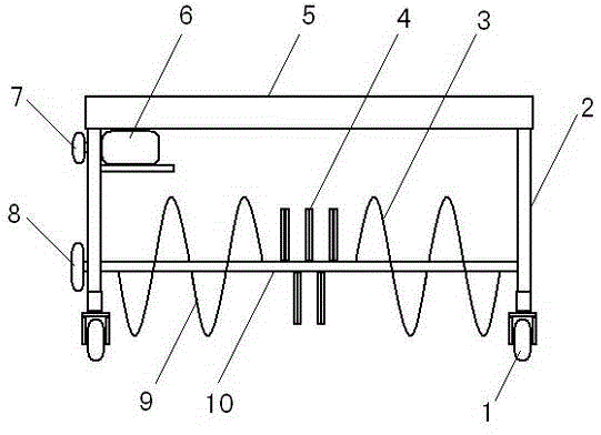
[0014] Such as figure 1 Shown, a kind of turning machine comprises ground wheel 1, frame 2, and frame 2 is cube-shaped, and frame 2 top is provided with shed plate 5, and shed plate 5 is rectangular, and shed plate 5 is used for blocking the flying material; the ground wheel 1 is set under the frame 2, and there are two kinds of ground wheels 1, namely, a walking wheel and a steering wheel, which are respectively placed at the front or rear of the frame (that is, the walking wheel can be placed at the front or the rear; the steering wheel can be placed at the front or at the rear), the travel motor (not shown in the figure) drives the sprocket C on the travel wheel through the chain, thereby driving the travel wheel, and then the machine automatically walks Main shaft 10 is also set on frame 2, and main shaft 10 is fixed on the frame 2 by bearing; On the main shaft 10, left and right ends are respectively provided with symmetrical right helical blade 3 and left helical blade 9...


PUM


Abstract

The invention relates to a machine, specifically to an upender. The upender comprises ground wheels and a rack, wherein the ground wheels are arranged below four corners of the rack; and two types of ground wheels are provided, i.e., walking wheels and steering wheels which are respectively arranged at the front part or the rear part of the rack. The upender is characterized in that a transverse main shaft is arranged on the rack; left spiral blades and right spiral blades in symmetry are respectively arranged at the left end and the right end of the main shaft; a plurality of cutters are arranged on the part of the main shaft between the left spiral blades and the right spiral blades; and the rack is provided with an upending motor, a chain wheel A of the upending motor and a chain wheel B for driving one end of the main shaft through a chain. The upender has the following beneficial effects: 1, the working intensity of operators is alleviated, and the upender can be easily operated by only one person; 2, the working efficiency in upending is effectively improved, and the working efficiency of one upender is approximate to the workload of 5 to 6 people; and 3, the upending effect is good and uniform, materials are pushed to a middle part by the left spiral blades and the right spiral blades and are further crushed by the cutters, so the materials can be upended uniformly and thoroughly.

Description

technical field [0001] The present invention relates to a machine, furthermore a machine for turning material, especially a machine for turning manure. Background technique [0002] In daily life, some stacking materials need to be turned over regularly. For example, if the pile of manure is not turned over in time (to facilitate exposure to sunlight and ventilation), it will easily produce odor due to internal fermentation, and at the same time, it will easily breed various pests; these will have a bad impact on the environment. [0003] At present, there is no suitable machine for material turning (manure turning), relying on manual material turning, which is labor-intensive and inefficient. Contents of the invention [0004] The object of the present invention is to provide a turning machine, which can effectively improve the working efficiency of turning and reduce labor intensity. [0005] The purpose of the present invention is achieved by the following scheme: ...

Claims


Application Information

Patent Timeline
Patent Type & Authority Applications(China)
IPC IPC(8): C05F17/02
CPCY02W30/40
Inventor 户尚伟
Owner 户尚伟
Why Eureka
Eureka Blog
Learn More