Improved laminar flow hood mechanism

A technology of laminar flow hood and cover, which is applied to the separation of dispersed particles, chemical instruments and methods, and filtration of dispersed particles. simple effect

Active Publication Date: 2016-02-17
SHANDONG ZHONGLI HIGH PRESSURE VALVE CO LTD
View PDF6 Cites 1 Cited by
  • Summary
  • Abstract
  • Description
  • Claims
  • Application Information

AI Technical Summary

Problems solved by technology

However, when the laminar flow hood is not working (or not working for a long time), the air inlet of the laminar flow hood is set on the top of the laminar flow hood, and it is inevitable that some dust layer impurities will accumulate on the filter screen of the air inlet, and even cause filtration Part of the filter hole on the net is blocked, so that the airflow cannot pass through the air inlet smoothly and enter the interior of the laminar flow hood for effective filtration, and the laminar flow hood is at a higher position, so an artificial shield is used to block the air flow into the laminar flow hood. The air outlet is more difficult

Method used


Image

  • Improved laminar flow hood mechanism
  • Improved laminar flow hood mechanism
  • Improved laminar flow hood mechanism

Examples


Embodiment Construction

[0022] The specific embodiments of the present invention will be described in further detail below in conjunction with the drawings and embodiments. The following examples are used to illustrate the present invention, but not to limit the scope of the present invention.

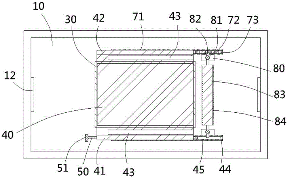
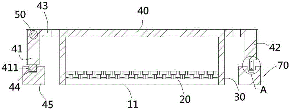
[0023] See figure 2 , The improved laminar flow hood mechanism of the present invention includes a hood 10 on which an air inlet 11 is formed, and a filter screen 20 covers the air inlet 11 and is fixed to the hood 10, A vertical rectangular ventilation duct 30 is fixed at the air inlet 11;

[0024] See Figure 1 to Figure 3 , The rectangular ventilation duct 30 is pressed against a rectangular cover plate 40, the two sides of the cover plate in the width direction extend out of the two sides of the rectangular ventilation duct 30, and the two sides of the cover plate 40 in the width direction are formed vertically downward The main moving part 41 and the auxiliary moving part 42 of the main moving part 41 are ...


PUM


Abstract

The invention discloses an improved laminar flow hood mechanism, which comprises a hood shell, wherein an air inlet is formed in the hood shell; a filter screen plate covers the air inlet and is fixed with the hood shell; a rectangular air duct pipeline is fixed at the air inlet; a cover plate presses the rectangular air duct pipeline; a vertical and downward main movement part and a vertical and downward auxiliary movement part are formed on two sides of the width direction of the cover plate; the main movement part sleeves and is screwed on a screw rod; a traveling wheel is hinged to the lower end of the auxiliary movement part and presses a movement guide rail; the movement guide rail comprises a base and a guiding slot formed in the upper end face of the base; a plurality of limiting grooves are formed in the inner wall of the lower end of the guiding slot; a hinged seat is fixed on the hood shell at one side of the rectangular air duct pipeline; a pair of vertical hinged rods is fixed on two ends of the hinged seat; a rotary shaft is hinged between the pair of hinged rods; a sticky roller sleeves the rotary shaft. When the laminar flow hood provided by the invention is not operated, the air inlet can be closed, the opening size of the air inlet can be adjusted, and the accumulated dust impurities can be cleaned.

Description

Technical field: [0001] The present invention relates to the technical field of purification laminar flow hoods, in particular to an improved laminar flow hood mechanism. Background technique: [0002] The laminar flow hood forms a flow-sharing layer after passing the air through the high-efficiency filter at a certain wind speed, so that the clean air flows in a vertical unidirectional manner, thereby ensuring the high cleanliness required by the process in the working area. There are two main ways to install the laminar flow hood, hanging installation and floor installation. However, regardless of whether it is a suspended or floor-standing laminar flow hood, the air inlet of the laminar flow hood is generally set at the top position of the laminar flow hood, and a layer of filter screen is generally set to achieve the initial filtering effect. However, when the laminar flow hood is not working (or left unused for a long time), the air inlet of the laminar flow hood is set on ...

Claims


Application Information

Patent Timeline
Patent Type & Authority Applications(China)
IPC IPC(8): B01D46/10B01D46/42
Inventor 冯义文
Owner SHANDONG ZHONGLI HIGH PRESSURE VALVE CO LTD
Why Eureka
Try Eureka