
Antenna structure and wireless device

An antenna structure and wireless device technology, applied in the field of communication, can solve problems such as difficult implementation and complex structure of the design scheme

Inactive Publication Date: 2016-02-10
LITE ON ELECTRONICS (GUANGZHOU) LTD +1
View PDF5 Cites 47 Cited by
  • Summary
  • Abstract
  • Description
  • Claims
  • Application Information

AI Technical Summary

Problems solved by technology

The design scheme structure of this kind of antenna structure is relatively complicated, and it is difficult to realize in actual production and production

Method used


Image

  • Antenna structure and wireless device
  • Antenna structure and wireless device
  • Antenna structure and wireless device

Examples


Embodiment Construction

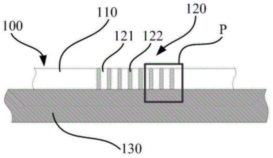
[0059] see figure 1 , which shows a partial cross-sectional view of the housing 100 according to the first embodiment of the present invention. The casing 100 is for example used in electronic equipment, especially handheld communication equipment.

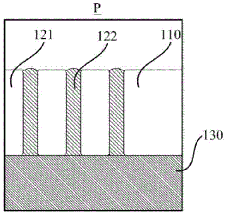
[0060] The casing 100 includes at least one metal body 110 and at least one invisible or low-visibility microlayer structure 120 . The microlayer structure 120 includes at least one metal layer 121 and at least one filling layer 122 . see figure 2 , which shows figure 1 Partial enlarged view at P in middle. Here, the metal layer 121 is composed of strip-shaped metal flakes extending perpendicular to the drawing. Filling layer 122 is made of an insulating material. Wherein, the metal layer and the filling layer are stacked alternately, thereby constituting a part of the antenna of the electronic device.

[0061] Optionally, the housing 100 may further include a strengthening layer 130 made of insulating material and attache...


PUM


Abstract

The invention relates to an antenna structure. The antenna structure comprises a shell and a main board, wherein the shell at least comprises a first metal body, a second metal body and at least one micro-layer structure; each micro-layer structure comprises stacked metal layers and filing layers; the micro-layer structures are positioned between the first metal body and the second metal body, and are completely or partially separated; a radiating element of the antenna structure is formed by one of the first metal body and the second metal body, a grounding element is formed by the other of the first metal body and the second metal body, and a matching element of the antenna structure is formed by the micro-layer structures; the main board at least comprises a main board body and necessary assistant circuit components and parts for enabling the metal shell to realize an antenna function; the radiating element is connected with the main board body through the assistant circuit components and parts, signals are processed and controlled by the assistant circuit components and parts, and the signals are transmitted by the radiating element; and the grounding element is connected with the main board body through the assistant circuit components and parts and is grounded. The invention also relates to a wireless structure of the antenna structure.

Description

technical field [0001] The present invention relates to antenna structures, and in particular to wireless devices. The invention belongs to the communication field. Background technique [0002] At present, in order to make electronic devices, such as handheld communication devices (usually including small portable computers, smart phones, etc.) more robust and to achieve more decorative effects, metals are widely used to replace traditional plastic materials as the shells of handheld communication devices. [0003] In order to further reduce the size of the entire device and make it more compact and portable, the metal shell or a part of the metal shell of the handheld communication device is often used as a component of the antenna in design. In order to avoid the influence of the good conductor metal shell on the antenna communication signal, it is generally necessary to open a gap in a specific part of the metal shell and fill the gap with a dielectric. However, openin...

Claims


Application Information

Patent Timeline
Patent Type & Authority Applications(China)
IPC IPC(8): H01Q1/44H01Q1/36H01Q1/24H05K5/04H05K5/02
Inventor 张允良陈世豪
Owner LITE ON ELECTRONICS (GUANGZHOU) LTD
Learn More