
Method for measuring light physical constants and device for estimating light physical constants

A measurement method and technology of photophysics, applied in the direction of measuring devices, optical instrument testing, testing optical fiber/optical waveguide equipment, etc., can solve problems such as the difficulty of optical physical constants and the distribution of optical physical constants

Active Publication Date: 2016-02-03
OSAKA UNIV
View PDF9 Cites 1 Cited by
  • Summary
  • Abstract
  • Description
  • Claims
  • Application Information

AI Technical Summary

Problems solved by technology

[0008] However, in the above-mentioned conventional method, it is assumed that the optical physical constant is measured under the premise that the optical physical constant of the optical transmission medium is constant, so it is difficult to obtain the optical physical constant depending on the position of the optical transmission medium, in other words, to obtain the distribution of the optical physical constant is difficult

Method used


Image

  • Method for measuring light physical constants and device for estimating light physical constants
  • Method for measuring light physical constants and device for estimating light physical constants
  • Method for measuring light physical constants and device for estimating light physical constants

Examples


Embodiment approach 1

[0045]

[0046] figure 1 It is a diagram showing the hardware configuration of the photophysical constant measurement system according to the first embodiment. The photophysical constant measurement system measures the power spectrum of the output optical signal, and uses the measured power spectrum to estimate the distribution of the photophysical constant of the optical transmission medium 120 .

[0047] The photophysical constant is a value indicating the characteristics of the interaction between electromagnetic waves and matter. Optical physical constants include: nonlinear optical constants and dispersion parameters. The nonlinear optical constants and dispersion parameters will be described later.

[0048] The optical transmission medium 120 is a medium for propagating optical signals, such as an optical fiber. The distribution of the optical physical constant in the light propagation direction in the optical transmission medium 120 is estimated by the optical physic...

Embodiment approach 2

[0116] Embodiment 2 will be described below.

[0117] The present embodiment differs from the first embodiment in that segments are merged during the search for the distribution of photophysical constants. Next, the photophysical constant estimation device according to the present embodiment will be described focusing on differences from the first embodiment. In addition, since the configuration of the photophysical constant measurement system according to the present embodiment is the same as figure 1 Same, omit illustration.

[0118]

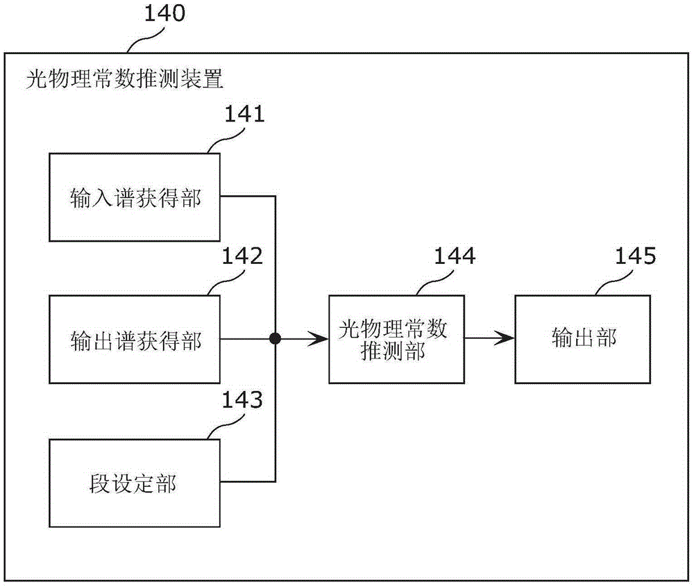
[0119] Figure 8 It is a block diagram showing the functional configuration of the optical physical constant estimation device 240 according to the second embodiment. in addition, Figure 8 with figure 2 Components with the same functions are assigned the same symbols, and explanations are appropriately omitted.

[0120] like Figure 8 As shown, the photophysical constant estimation device 240 includes an input spectrum acquisition uni...


PUM


Abstract

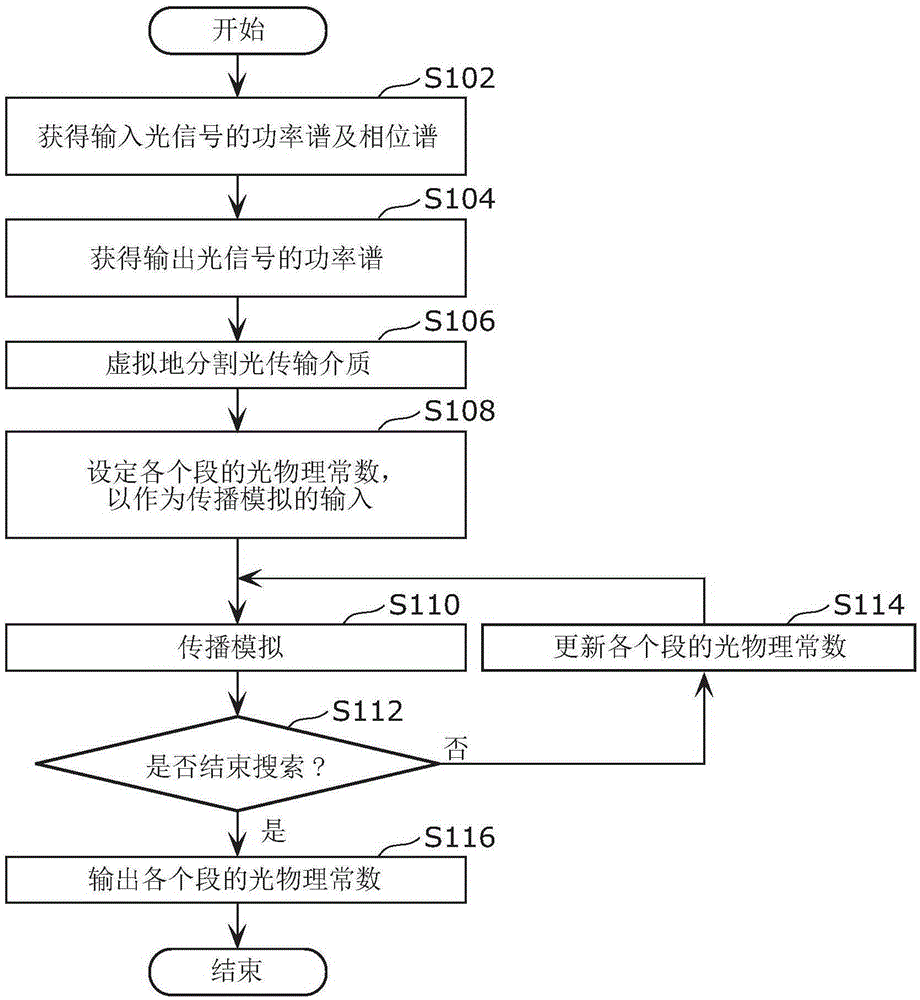
A method for measuring light physical constants includes a dividing step (S106) of setting a plurality of first segments by dividing, virtually, an optical transmission medium along the direction of propagation, and a first estimating step (S108 - S114) of estimating the light physical constants for the plurality of first segments on the basis of a first propagation simulation result by way of a model for which input optical signals having various intensities are propagated in order in the plurality of first segments. For the first estimating step, the light physical constants for the plurality of first segments are estimated by performing a search for the light physical constants for the plurality of first segments using an evaluation function that evaluates the difference between a power spectrum of a measured output optical signal and a power spectrum of an output optical signal obtained as the result of the first propagation simulation result.

Description

technical field [0001] The present invention relates to a method of estimating the distribution of photophysical constants of an optical transmission medium. Background technique [0002] In the field of optical communication, the optical physical constants of the optical transmission medium (for example, nonlinear optical constants or dispersion parameters, etc.) affect the transmission characteristics of optical signals. Then, a method of measuring the photophysical constant of an optical transmission medium has been proposed (for example, refer to Non-Patent Document 1). [0003] (Prior art literature) [0004] (non-patent literature) [0005] Non-Patent Document 1: Toshiharu Yukita, Atsushi Honda, "User Engineer's Guide to Optical Measuring Instruments", OPTRONICS Corporation, 1999, pp.102-126 [0006] Summary of Invention [0007] Invention to solve problem [0008] However, in the above-mentioned conventional method, it is assumed that the optical physical constan...

Claims


Application Information

Patent Timeline
IPC IPC(8): G01M11/02
CPCG01M11/3145G01M11/33G01M11/338G01M11/333
Inventor 小西毅高桥考二川西健太郎
Owner OSAKA UNIV
Learn More