
Method and circuit for confirming correctness of signal and charging system using same

A charging system and correctness technology, applied in circuit devices, battery circuit devices, data exchange chargers, etc., can solve problems such as inaccurate signals, inaccurate voltages, and incorrect signals

Inactive Publication Date: 2016-02-03
RICHTEK TECH
View PDF7 Cites 2 Cited by
  • Summary
  • Abstract
  • Description
  • Claims
  • Application Information

AI Technical Summary

Problems solved by technology

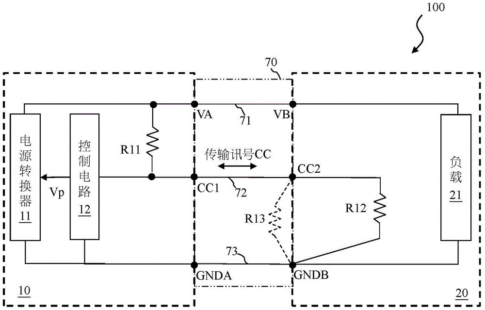
[0003] Under normal conditions, the voltage of node CC2 is equal to VA*R12 / (R11+R12); however, under abnormal conditions, when there is dust or dirt on the port connecting the electronic device 20 and the cable 70, it may cause a negative power supply Another conduction path between the transmission line 73 and the signal transmission line 72 is represented by a dashed resistor R13
As a result, the voltage of the node CC2 will be out of alignment, causing the signal provided from the electronic device 20 via the node CC2 to be incorrect.
The defect of this prior art is that the charging system 100 cannot know whether the signal provided by the electronic device 20 (power receiving end) via the node CC2 is correct or not.

Method used


Image

  • Method and circuit for confirming correctness of signal and charging system using same
  • Method and circuit for confirming correctness of signal and charging system using same
  • Method and circuit for confirming correctness of signal and charging system using same

Examples


Embodiment Construction

[0023] The aforementioned and other technical contents, features and effects of the present invention will be clearly presented in the following detailed description of a preferred embodiment with reference to the drawings. The drawings in the present invention are all schematic, mainly intended to show the functional relationship between each device and each component, as for the shape, size, and direction, they are not drawn according to the scale of the actual object.

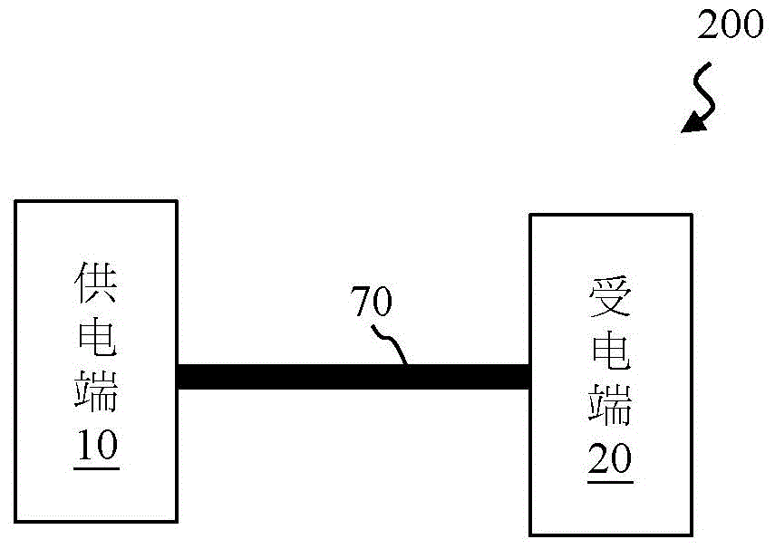
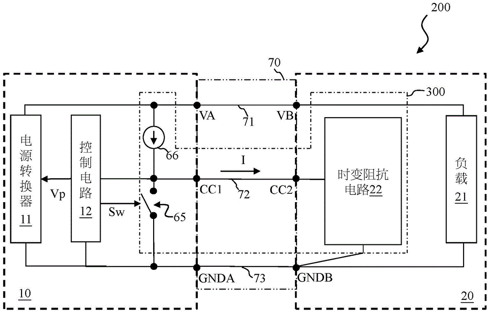
[0024] Please refer to Figure 2A-2B and Figure 3A . Figure 2A-2B A schematic block diagram of a charging system according to an embodiment of the present invention is shown. Figure 3A Mark an embodiment of the charging system of the present invention when it is connected normally. like Figure 2A As shown, the charging system 200 of this embodiment includes a power supply terminal 10 , a cable 70 and a power receiving terminal 20 . The power supply terminal 10 and the power receiving terminal 20 are...


PUM


Abstract

The invention provides a method and circuit for confirming correctness of a signal and a charging system using same. A method for confirming correctness of a signal includes: providing a current to flow through a time-dependent impedance circuit, wherein the time-dependent impedance circuit provides at least two resistances at two different time points, the current flowing through the time-dependent impedance circuit to generate a first voltage at a first time point, and the current flowing through the time-dependent impedance circuit to generate a second voltage at a second time point, the first voltage and the second voltage being different from each other. When a predetermined relationship exists between the first voltage and the second voltage, it is confirmed that a signal provided from a node coupled to the time-dependent impedance circuit is correct.

Description

technical field [0001] The present invention relates to a method and circuit for confirming the correctness of signals and a charging system using the circuit, in particular to a method and circuit for confirming the correctness of signals through the voltage variation relationship, and a charging system using the circuit. Background technique [0002] Please refer to figure 1 , which shows a schematic block diagram of a prior art charging system. like figure 1 As shown, the prior art charging system 100 includes a power supply 10 , a cable 70 and an electronic device 20 . The power supply 10 and the electronic device 20 are coupled to each other via a cable 70 . The power supply 10 includes a power converter 11 and a control circuit 12 , wherein the control circuit 12 controls the operation of the power converter 11 . The electronic device 20 includes a load 21 . The cable 70 includes a positive power transmission line 71 , a negative power transmission line 73 and a s...

Claims


Application Information

Patent Timeline
Patent Type & Authority Applications(China)
IPC IPC(8): H02J7/00G01R19/00
CPCG01R31/69H02J7/00038H02J7/00036H02J7/00047H02J7/007
Inventor 朱益杉尹治平杨世仁
Owner RICHTEK TECH
Learn More