
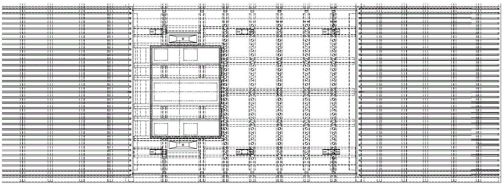
Ceiling fault surface structure of urban rail stainless steel vehicle

A stainless steel and vehicle technology, applied in the field of urban rail stainless steel vehicle roof section structure, can solve the problems of reduced production efficiency, large welding volume, unstable height difference, etc., to simplify the production process, reduce material costs, and improve production efficiency. Effect

Inactive Publication Date: 2016-02-03
CRRC DALIAN CO LTD
View PDF6 Cites 13 Cited by
  • Summary
  • Abstract
  • Description
  • Claims
  • Application Information

AI Technical Summary

Problems solved by technology

The top of the air-conditioning platform and the pantograph platform is lower than the corrugated roof area. Such a roof structure has high requirements on the assembly and welding process of the components. After the welding is completed, the deflection of the entire roof is not easy to control. Poor height control between pantograph platform bottom and vehicle floor, unstable on height difference
In addition, due to the long distance between the inner roof and the curved beam at the corrugated plate of the ceiling, small steel structure parts with secondary transitions are required. The number of such small parts is relatively large, and the shape is complex and the welding volume is large.
Such weldments are not conducive to vehicle weight reduction, reduce production efficiency, and increase design and production costs

Method used


Image

  • Ceiling fault surface structure of urban rail stainless steel vehicle
  • Ceiling fault surface structure of urban rail stainless steel vehicle
  • Ceiling fault surface structure of urban rail stainless steel vehicle

Examples


Embodiment Construction

[0024] Attached below figure 1 to attach Figure 13 To further illustrate the present invention, the urban rail stainless steel vehicle roof steel structure includes two upper string beams 2 and a plurality of curved beams 5 arranged transversely to the upper string beams 2 and spaced in parallel. On the surface 12, the top surfaces of the two ends of the curved beam 5 are engaged with the side roof 1 respectively, and the middle top surface of the curved beam 5 is provided with a covering surface, and the covering surface is composed of the corrugated plate area and the arc plate area to form the same plane, and the corrugated plate area and the arc plate The areas are connected by arc welding, and the air-conditioning platform 9 is set in the arc plate area; the top surface of the corrugated plate area and the top surface of the arc plate area are on the same plane. That is to say, the amount of connecting small parts in the corrugated plate area and the arc plate area is r...


PUM


Abstract

The invention discloses a ceiling fault surface structure of an urban rail stainless steel vehicle. The ceiling fault surface structure comprises two upper chord beams and a plurality of curved beams which are laterally arranged at intervals on the upper chord beams in parallel, wherein two ends of each of the curved beams are respectively butted against on the positioning surfaces of the upper chord beams; the top surfaces of two ends of each of the curved beams are respectively combined with a side top plate in a clamping manner; a covering surface is arranged on the upper central surfaces of curved beams; the covering surface comprises a corrugated plate region and an arc plate region which are in arc welding connection; an air conditioner platform is arranged in the arc plate region; the top surface of the corrugated plate region and the top surface of the arc plate region are on the same plane. The novel stainless steel ceiling fault surface structure effectively solves the problem of light weight design of a vehicle body structure, the weight of the vehicle body structure per unit length can be reduced by about 20kg, the production technology flows are simplified, and the production efficiency is improved. Material consumption is reduced, so that the material cost is reduced. The number of small built-in steel structure components is obviously reduced, the small components are simple in structure and easy to produce and weld, and a design basis is provided for the novel stainless steel vehicle body structure.

Description

technical field [0001] The invention relates to the technical field of vehicle body structure, in particular to a section structure of a roof section structure of an urban rail stainless steel vehicle. Background technique [0002] At present, the roof steel structure of urban rail stainless steel vehicles is mainly assembled and welded by air-conditioning platform, pantograph platform, upper string beam, curved beam, corrugated plate and other components of the roof into a whole roof structure, such as figure 1 shown. The top of the air-conditioning platform and the pantograph platform is lower than the corrugated roof area. Such a roof structure has high requirements on the assembly and welding process of the components. After the welding is completed, the deflection of the entire roof is not easy to control. The height control between the bottom of the pantograph platform and the vehicle floor is not good, and the height difference is unstable. In addition, due to the l...

Claims


Application Information

Patent Timeline
IPC IPC(8): B61D17/12
Inventor 刘军王斌马文杰
Owner CRRC DALIAN CO LTD
Learn More