
A dual-purpose shoulder joint body position frame

A shoulder joint and body position technology, which is applied in the direction of stereotaxic surgical instruments, etc., can solve the problems of long time for shoulder arthroscopy, difficult long-term and effective implementation of manual labor, and pollution of the surgical field, so as to reduce the labor intensity of assistants, improve efficiency, and reduce Effect of surgical infection risk

Active Publication Date: 2016-10-12
吴江科技创业园管理服务有限公司
View PDF6 Cites 0 Cited by
  • Summary
  • Abstract
  • Description
  • Claims
  • Application Information

AI Technical Summary

Problems solved by technology

There are currently deficiencies in the manual way of revealing: 1. Due to the relatively long operation time of shoulder arthroscopy, especially in grass-roots hospitals, it is a great challenge to the physical strength of the assistants; 3. It is difficult to maintain an effective wound exposure after the assistant is tired; 4. Some angles that require ideal exposure are currently difficult to achieve long-term and effective artificially

Method used


Image

  • A dual-purpose shoulder joint body position frame
  • A dual-purpose shoulder joint body position frame
  • A dual-purpose shoulder joint body position frame

Examples


Embodiment 1

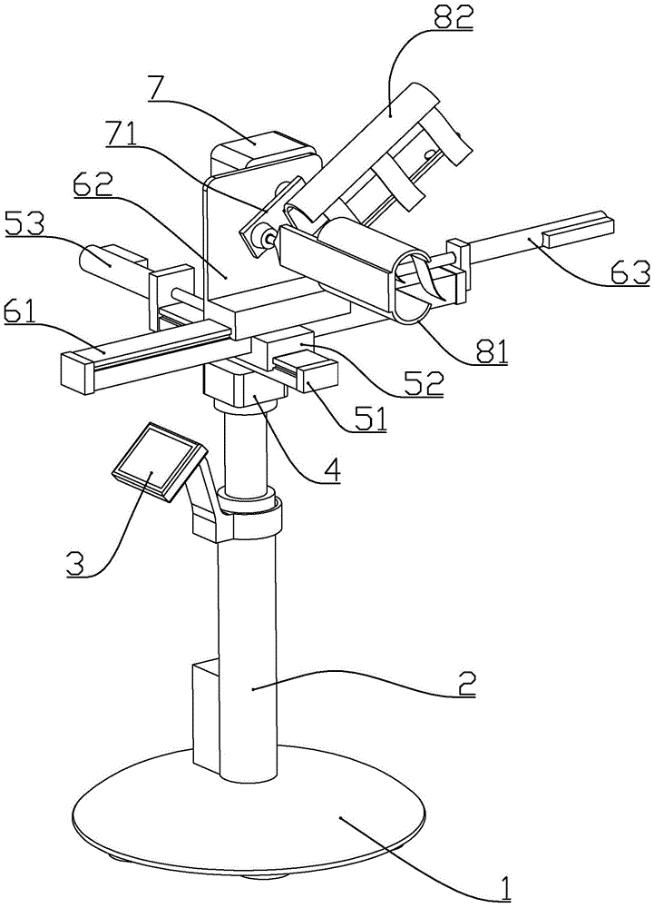
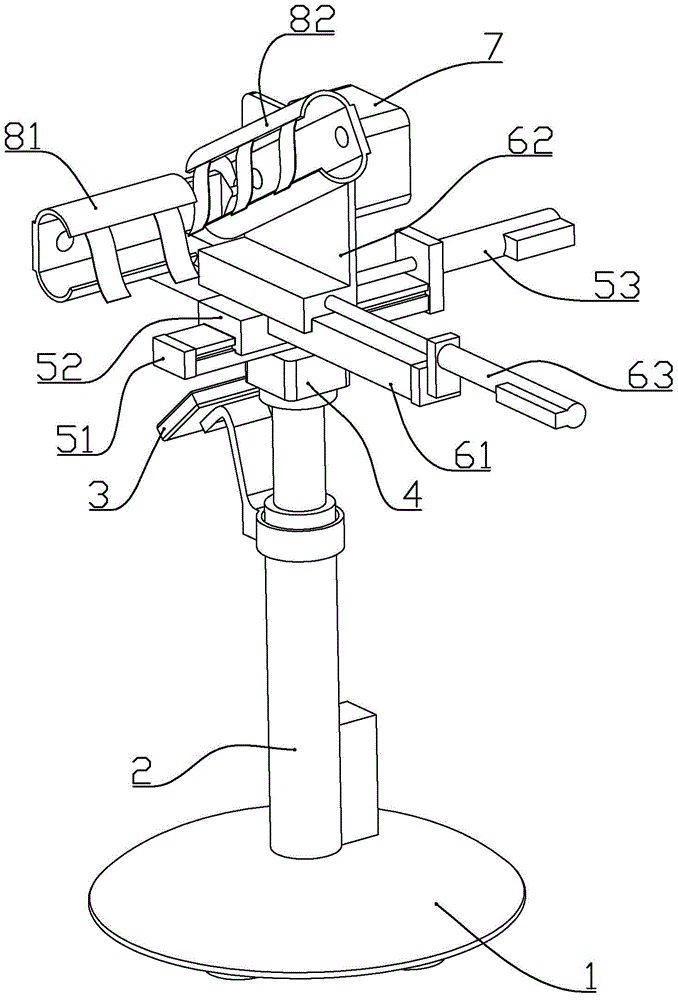
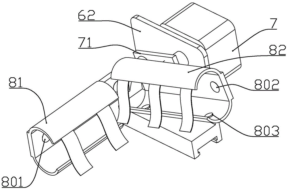
[0019] according to Figure 1 to Figure 4 As shown, a dual-purpose shoulder joint body position frame described in this embodiment includes a base 1, a height adjustment push rod 2 vertically installed on the base, a control panel 3 installed on the side of the height adjustment push rod, fixedly connected The first motor 4 at the end of the output shaft of the height adjustment push rod is fixedly connected to the first slide rail 51 on the output shaft of the first motor, and the first slider 52 that is slidably installed on the first slide rail is installed on the first slide rail. One end of the slide rail and the first electric cylinder 53 whose output shaft is connected to the first slide block, the second slide rail 61 fixedly connected above the first slide block, the second slide block 62 slidably installed above the second slide rail, and A second electric cylinder 63 that is installed at one end of the second slide rail and whose output shaft is connected with the s...

Embodiment 2

[0031] The difference between this embodiment and Embodiment 1 is that three tightness adjustment motors are installed on a rubber plate or base plate on the boom fixing frame and the forearm fixing frame, and three tightness adjustment motors are installed on the output shaft of the tightness adjustment motor. a pulley, the upper end of the fixed belt is fixedly connected to the pulley. In this way, after the fixing belt is connected with another rubber plate, the tightness of the fixing belt can be adjusted by the tightness adjustment motor, so that the force on each position of the arm is uniform, and it is convenient to set the initial pressure of each pressure sensor in an appropriate range (for example, by adjusting the fixing belt Tightness, so that the initial pressure of each pressure sensor is half of the measured value of the pressure sensor), which is beneficial for the pressure sensor to obtain more accurate signals when the arm moves.


PUM


Abstract

The invention discloses a dual-purpose shoulder joint position frame, which includes a base, a height adjustment push rod installed on the base, a control panel installed on the side of the height adjustment push rod, and a second shaft connected to the output shaft end of the height adjustment push rod. A motor, a first slide rail connected to the output shaft of the first motor, a first slide block slidably installed on the first slide rail, a first slide block installed at one end of the first slide rail and the output shaft connected to the first slide block An electric cylinder, a second sliding rail connected above the first sliding block, a second sliding block slidably installed above the second sliding rail, and a second sliding block installed at one end of the second sliding rail and the output shaft connected to the second sliding block electric cylinder; a second motor is installed on the second slider, a connection plate is connected to the output shaft of the second motor, a small arm fixing frame is connected to the connection plate, and a large arm is connected to the connection plate through a ball joint bearing Fixing frame; the body position frame can be used for adjusting the body position of the shoulder joint during shoulder arthroscopic surgery, and can also be used for assisting patients to move their arms after operation.

Description

technical field [0001] The invention belongs to the field of medical equipment, and in particular relates to a shoulder joint posture frame. Background technique [0002] Shoulder arthroscopy is currently the most commonly used clinical method for the diagnosis and treatment of shoulder joint diseases. If there is a loose body in the joint, make a clear diagnosis and remove the loose body; if the painful joint is unstable, shoulder arthroscopic surgery can be used to make a clear diagnosis Joint capsule , Labrum damage, possible repair surgery; biceps rupture can understand the extent of the rupture, cut off the end, relieve pain ;Rotator cuff rupture, in acute and complete rotator cuff injury, arthroscopic examination is not suitable due to fluid leakage of the joint capsule. For chronic rotator cuff rupture, the lesion can be clarified, and incomplete injury can be trimmed to relieve pain; Osteoarthritis Debridement and irrigation can be performed under shoulder arthro...

Claims


Application Information

Patent Timeline
Patent Type & Authority Patents(China)
IPC IPC(8): A61B90/14
Inventor 王波季卫平刘斌范秋平许超
Owner 吴江科技创业园管理服务有限公司
Learn More