
System monitoring apparatus and method

A system monitoring and monitored technology, applied in the direction of comprehensive factory control, comprehensive factory control, electrical program control, etc., can solve problems such as difficult to show performance

Inactive Publication Date: 2016-01-27
SAMSUNG SDS CO LTD
View PDF3 Cites 0 Cited by
  • Summary
  • Abstract
  • Description
  • Claims
  • Application Information

AI Technical Summary

Problems solved by technology

Furthermore, for systems with high complexity, it is difficult for the dichotomous decision as described above to exhibit satisfactory performance

Method used


Image

  • System monitoring apparatus and method
  • System monitoring apparatus and method
  • System monitoring apparatus and method

Examples


Embodiment Construction

[0080] Hereinafter, specific embodiments of the present invention will be described with reference to the drawings. The following detailed description is provided to facilitate a comprehensive understanding of the methods, devices and / or systems described in this specification. However, this is just an example, and the present invention is not limited thereto.

[0081] When describing the present invention, if it is considered that the specific description of the known technology related to the present invention may cause unnecessary confusion to the gist of the present invention, the detailed description will be omitted. In addition, terms described later are terms defined in consideration of functions in the present invention, and may vary depending on users, operator's intentions, practices, and the like. Therefore, it should be defined on the basis of the content throughout the entire specification. The terms used in the detailed description are for describing the embodi...


PUM


Abstract

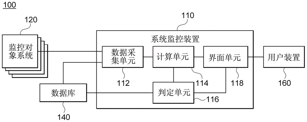
The invention discloses a system monitoring apparatus and a method. The system monitoring apparatus in the embodiment comprises a data collection unit that collects a first data set obtained from the monitored system and judged to represent the state of the system and a second data set obtained from the system; a calculating unit that calculates an index related to the state of the system based on the first data set and the second data set.

Description

technical field [0001] The disclosed embodiments relate to a system monitoring device and method, and more specifically, to a technique for diagnosing and indexing system status. Background technique [0002] With the development of information communication technology, the demand for a service of arranging various types of sensors in buildings and controlling devices in the buildings based on sensor values ​​has greatly increased. The status of systems providing these services can be monitored based on sensor values. Typically, such system monitoring is accompanied by a determination of whether the system is functioning properly or has a defect in the system. [0003] However, existing system monitoring methods are not useful for detecting potential defects in the system. This is because, in general, existing methods merely inform the user that a defect has occurred, and set a defensive threshold to determine that the condition has occurred based on only a small possibili...

Claims


Application Information

Patent Timeline
IPC IPC(8): G05B19/418
CPCY02P90/02
Inventor 吴圭三金炯赞徐范准权纯焕赵常元
Owner SAMSUNG SDS CO LTD
Learn More