Vibration resistance installation method for temperature compensation crystal oscillator

An installation method and technology of temperature-compensated crystal oscillator, which are applied in the field of satellite navigation, can solve the problems of reducing satellite signal acquisition, tracking performance, deterioration of crystal oscillator phase noise indicators, etc., and achieve the effect of reducing overall vibration and improving acquisition.

Active Publication Date: 2016-01-27
BEIJING AUTOMATION CONTROL EQUIP INST
View PDF4 Cites 3 Cited by
  • Summary
  • Abstract
  • Description
  • Claims
  • Application Information

AI Technical Summary

Problems solved by technology

Under static conditions, this type of index is better; in the actual working environment, there are many shocks, vibrations, accelerations, etc., which will cause the deterioration of the phase noise index of the crystal oscillator, thereby reducing the receiver's ability to capture and track satellite signals

Method used


Image

  • Vibration resistance installation method for temperature compensation crystal oscillator
  • Vibration resistance installation method for temperature compensation crystal oscillator
  • Vibration resistance installation method for temperature compensation crystal oscillator

Examples


Embodiment 1

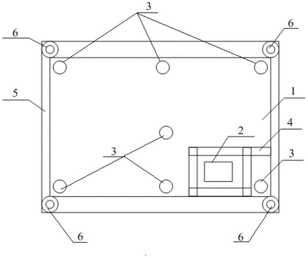
[0017] figure 1 Shown is the installation position of the crystal oscillator 2 on the circuit board 1. The crystal oscillator should be as far away from the center of the circuit board as possible with the largest vibration amplitude, and located at the corner of the circuit board 1 or near the mounting hole 3. The circuit board 1 passes through the mounting hole 3 and screws are fixed on the base.

Embodiment 2

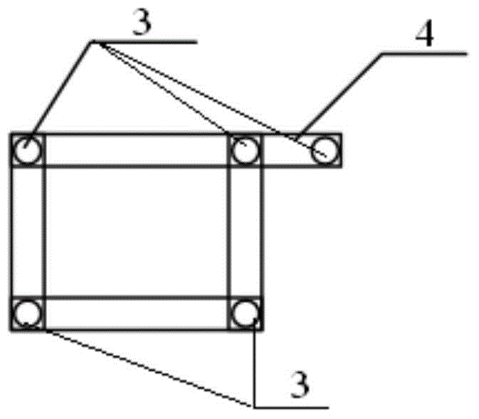
[0019] On the basis of Embodiment 1, a reinforcement structure 4 is arranged around the crystal oscillator 2 to enhance the local rigidity of the circuit board, and the reinforcement structure 4 is as figure 2 As shown, it is in the shape of a quadrangular frame, and the crystal oscillator 2 is enclosed inside the quadrangular frame, and mounting holes 3 are provided on the four corners of the quadrangular frame, and one of the long sides of the quadrangular frame extends to the edge of the circuit board, where it extends An installation hole 3 is also provided at the end of the direction, and the reinforcement structure 4 is connected with the circuit board 1 as a whole through screws and the installation hole 3 .

Embodiment 3

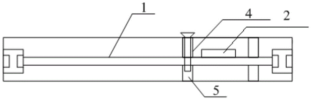
[0021] On the basis of Embodiment 2, a shell structural member 5 is also provided outside the circuit board 1. The upper end of the shell structural member 5 is closed, the bottom surface is open, and the shape of the surrounding is consistent with the shape of the circuit board 1. Above the board 1, a boss is provided at the corresponding installation position of the reinforcement structure 4 on the inner side of the shell structure 5, which is used to reduce the vibration of the circuit board and facilitate installation. At the position where the boss corresponds to the mounting hole 3 on the reinforcement structure 4, a mounting hole 3 is also provided, and the circuit board 1, the reinforcement structure 4 and the shell structure 5 pass through the mounting hole 3 and through the mounting hole. 3 screws are fixedly connected as one, such as image 3 shown.


PUM


Abstract

The invention belongs to the technical field of satellite navigation, and concretely relates to a vibration resistance installation method for a temperature compensation crystal oscillator. The technical effects of the invention are that the provided vibration resistance installation method has a good vibration damping effect, is easy to realize and minimizes the influence of vibration upon a crystal oscillator. According to the vibration resistance installation method, a crystal oscillator is far from the central position, with the greatest vibration amplitude, of a circuit board as much as possible, and is placed in a corner of the circuit board or close to an installation hole, and the circuit board is fixed to a pedestal through installation holes and screws. Through the vibration resistance installation method, the overall vibration of a circuit board and the local vibration of the installation position of a temperature compensation crystal oscillator can be effectively reduced, so the short-term frequency stability and the phase noise of the temperature compensation crystal oscillator keep having good indexes, and then the performance of a receiver to capture and track satellite signals is improved.

Description

technical field [0001] The invention belongs to the technical field of satellite navigation, and in particular relates to an anti-vibration installation method of a temperature-compensated crystal oscillator. Background technique [0002] In the satellite navigation receiver, the temperature-compensated crystal oscillator is used as a reference to generate the local oscillator frequency, and its short-term frequency stability, phase noise and other indicators have a great impact on the performance of the receiver. Under static conditions, this type of index is better; in the actual working environment, there are many shocks, vibrations, accelerations, etc., which will cause the deterioration of the phase noise index of the crystal oscillator, and then reduce the receiver's ability to capture and track satellite signals. Contents of the invention [0003] The technical problem to be solved in the present invention is to provide a temperature-compensated crystal oscillator i...

Claims


Application Information

Patent Timeline
Patent Type & Authority Applications(China)
IPC IPC(8): G01S19/13
Inventor 尹真李峰原海军武成锋左启耀
Owner BEIJING AUTOMATION CONTROL EQUIP INST
Why Eureka
Try Eureka