a bracket
A technology of supporting feet and supporting rods is applied in the field of brackets, which can solve the problems of cumbersome construction of brackets, inconvenient storage and carrying, etc., and achieve the effects of protecting property safety, being convenient to carry and adjusting, and protecting personal safety.
- Summary
- Abstract
- Description
- Claims
- Application Information
AI Technical Summary
Problems solved by technology
Method used
Image
Examples
Embodiment 1
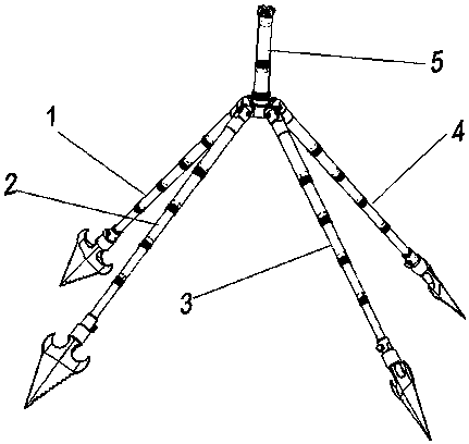
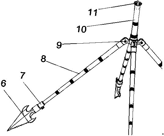
[0056] Embodiment 1: as Figure 1-26 As shown, a bracket includes an adjustable leg 1, an adjustable leg 2, an adjustable leg 3, an adjustable leg 4, and a support rod adjustment and fixing device 5;
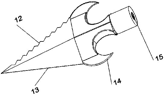
[0057] The structure of the adjustable leg one 1, the adjustable leg two 2, the adjustable leg three 3, and the adjustable leg four 4 are all the same and include a leg fixing mechanism 6, a rotary ball valve rotation mechanism 7, a telescopic rod height adjustment mechanism 8, a leg The root adjustment mechanism 9; wherein one end of the leg fixing mechanism 6 is fixed on the ground, the other end of the leg fixing mechanism 6 is screwed tightly to one end of the rotating ball valve rotating mechanism 7, and the other end of the rotating ball valve rotating mechanism 7 is connected to one end of the telescopic rod height adjusting mechanism 8 , the other end of the telescopic rod height adjustment mechanism 8 is connected with one end of the leg root adjustment mechanism 9 .
...
Embodiment 2
[0067] Embodiment 2: as Figure 1-26 As shown, a bracket includes an adjustable leg 1, an adjustable leg 2, an adjustable leg 3, an adjustable leg 4, and a support rod adjustment and fixing device 5;
[0068] The structure of the adjustable leg one 1, the adjustable leg two 2, the adjustable leg three 3, and the adjustable leg four 4 are all the same and include a leg fixing mechanism 6, a rotary ball valve rotation mechanism 7, a telescopic rod height adjustment mechanism 8, a leg The root adjustment mechanism 9; wherein one end of the leg fixing mechanism 6 is fixed on the ground, the other end of the leg fixing mechanism 6 is screwed tightly to one end of the rotating ball valve rotating mechanism 7, and the other end of the rotating ball valve rotating mechanism 7 is connected to one end of the telescopic rod height adjusting mechanism 8 , the other end of the telescopic rod height adjustment mechanism 8 is connected with one end of the leg root adjustment mechanism 9 .
...
Embodiment 3
[0076] Embodiment 3: as Figure 1-26 As shown, a bracket includes an adjustable leg 1, an adjustable leg 2, an adjustable leg 3, an adjustable leg 4, and a support rod adjustment and fixing device 5;
[0077] The structure of the adjustable leg one 1, the adjustable leg two 2, the adjustable leg three 3, and the adjustable leg four 4 are all the same and include a leg fixing mechanism 6, a rotary ball valve rotation mechanism 7, a telescopic rod height adjustment mechanism 8, a leg The root adjustment mechanism 9; wherein one end of the leg fixing mechanism 6 is fixed on the ground, the other end of the leg fixing mechanism 6 is screwed tightly to one end of the rotating ball valve rotating mechanism 7, and the other end of the rotating ball valve rotating mechanism 7 is connected to one end of the telescopic rod height adjusting mechanism 8 , the other end of the telescopic rod height adjustment mechanism 8 is connected with one end of the leg root adjustment mechanism 9 .
...
PUM
 Abstract
Description
Claims
Application Information
 - R&D
- Intellectual Property
- Life Sciences
- Materials
- Tech Scout
- Unparalleled Data Quality
- Higher Quality Content
- 60% Fewer Hallucinations
Browse by: Latest US Patents, China's latest patents, Technical Efficacy Thesaurus, Application Domain, Technology Topic, Popular Technical Reports.
© 2025 PatSnap. All rights reserved.Legal|Privacy policy|Modern Slavery Act Transparency Statement|Sitemap|About US| Contact US: help@patsnap.com


