Linear guide shaft type anti-swing suction cup movement mechanism

A motion mechanism and suction cup technology, applied in the directions of transportation and packaging, sending objects, thin material processing, etc., can solve the problems of scratches on the surface of the sheet, affecting the quality of the sheet, and the gap between the positions of the stacks, etc., to achieve motion displacement and accurate rotation angle, improve structural stability, and improve the effect of space utilization.

Inactive Publication Date: 2016-01-27
CENTRAL SOUTH UNIVERSITY OF FORESTRY AND TECHNOLOGY
View PDF11 Cites 1 Cited by
  • Summary
  • Abstract
  • Description
  • Claims
  • Application Information

AI Technical Summary

Problems solved by technology

[0004] 1. The boards are not neatly stacked. After the boards are stacked, the boards are not in a straight line along the vertical direction, which is easy to cause inverted stacking, that is, damage to the boards also brings safety hazards
[0005] 2. The stacking space of the sheets is not fully utilized, the intervals between the stacks are different, and the utilization rate of the storage space for the sheets is low
[0006] 3. The magnification of sheet metal often requires manual handling and counting, and the level of automation is not high
[0007] 4. The stacking of sheets through automatic grabbing equipment or belt transmission equipment may easily cause scratches on the surface of the sheet and affect the quality of the sheet
[0008] 5. The efficiency of sheet stacking is low, which cannot meet the requirements of fast storage and logistics

Method used


Image

  • Linear guide shaft type anti-swing suction cup movement mechanism
  • Linear guide shaft type anti-swing suction cup movement mechanism
  • Linear guide shaft type anti-swing suction cup movement mechanism

Examples


Embodiment Construction

[0040] Combine below Figure 1 to Figure 10 Embodiments of the present invention are described in detail.

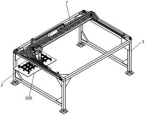
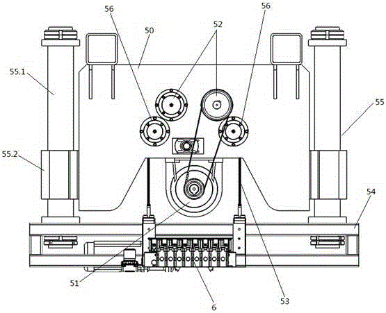
[0041] like figure 1 As shown, the linear guide shaft type anti-sway suction cup movement mechanism includes a rectangular parallelepiped frame-shaped frame 1 and a suction cup assembly 2 for absorbing sheet materials. The suction cup assembly 2 is placed in the frame 1, and the suction cup assembly 2 is provided in The Y-axis power assembly 3 that moves power along the width direction of the frame 1 in the frame 1, the X-axis power assembly 4 that provides the power for the suction cup assembly 2 to move along the length direction of the frame 1 in the frame 1, and provides the suction cup assembly 2 on the frame 1, the Z-axis power assembly 5 that lifts power along the height direction of the frame 1 and the P-axis rotation power assembly 6 that provides the horizontal rotation power of the suction cup assembly 2, the Y-axis power assembly 3, the X-axis power assembly...


PUM


Abstract

A linear guide shaft type anti-swing suction cup movement mechanism comprises a rack in a cuboid vertical frame shape and a suction cup assembly used for adsorbing plates. The suction cup assembly is arranged in the rack. The linear guide shaft type anti-swing suction cup movement mechanism is characterized in that a Y-axis power assembly, an X-axis power assembly, a Z-axis power assembly and a P-axis rotation power assembly are further included; the Y-axis power assembly is used for providing power for movement, in the width direction of the rack, of the suction cup assembly in the rack; the X-axis power assembly is used for providing power for movement, in the length direction of the rack, of the suction cup assembly in the rack; the Z-axis power assembly is used for providing power for ascending and descending, in the height direction of the rack, of the suction cup assembly in the rack; the P-axis rotation power assembly is used for providing power for horizontal rotation of the suction cup assembly; and the running states of the Y-axis power assembly, the X-axis power assembly, the Z-axis power assembly, the P-axis rotation power assembly and the suction cup assembly are uniformly controlled by a control system. According to the linear guide shaft type anti-swing suction cup movement mechanism, the plates are stacked rapidly and orderly, the automation level and efficiency of stacking the plates are improved, and the storage space utilization rate of the plates is increased.

Description

technical field [0001] The invention relates to a movement mechanism, mainly a linear guide shaft type anti-sway suction cup movement mechanism, which is used for automatically stacking sheets. Background technique [0002] Sheet metal is widely used in industry and life, such as automobiles, refrigerators, washing machines, high-end furniture, cabinet equipment, industrial and civil buildings, etc. In recent years, in the furniture production industry, the use of PCM color-coated sheets has gradually emerged as the molding material for its side panels and panels. Therefore, the requirements for the appearance are gradually increasing, and the storage and transportation of the sheet should avoid scratching the surface of the sheet as much as possible to ensure that the appearance of the sheet will not be affected. The effective stacking of sheets is the basis for the storage and transportation of sheets. [0003] The main defects of sheet material stacking in the prior a...

Claims


Application Information

Patent Timeline
Patent Type & Authority Applications(China)
IPC IPC(8): B65H29/32
Inventor 高自成李立君李舟肖诗慧
Owner CENTRAL SOUTH UNIVERSITY OF FORESTRY AND TECHNOLOGY
Why Eureka
Try Eureka