Liquid ejection head and manufacturing method of liquid ejection head

一种液体喷出头、制造方法的技术,应用在印刷等方向,能够解决剥离、硅基板破裂、构件剥离等问题,达到抑制剥离的效果

Active Publication Date: 2016-01-27
CANON KK
View PDF10 Cites 3 Cited by
  • Summary
  • Abstract
  • Description
  • Claims
  • Application Information

AI Technical Summary

Problems solved by technology

That is, due to the residual stress of the silicon substrate and the difference in the coefficient of linear expansion between the silicon substrate and the supporting member, each of the silicon substrate and the supporting member expands due to temperature changes in use of the liquid ejection head and Synergy between shrinkage, the silicon substrate may be cracked, or the ejection port forming member may be peeled off from the silicon substrate
In particular, since the printing element substrate becomes slender or narrow at high density, concerns arise about cracking of the silicon substrate or peeling of the ejection port forming member

Method used


Image

  • Liquid ejection head and manufacturing method of liquid ejection head
  • Liquid ejection head and manufacturing method of liquid ejection head
  • Liquid ejection head and manufacturing method of liquid ejection head

Examples


no. 1 approach

[0030] A first embodiment of the present invention will be described below with reference to the drawings.

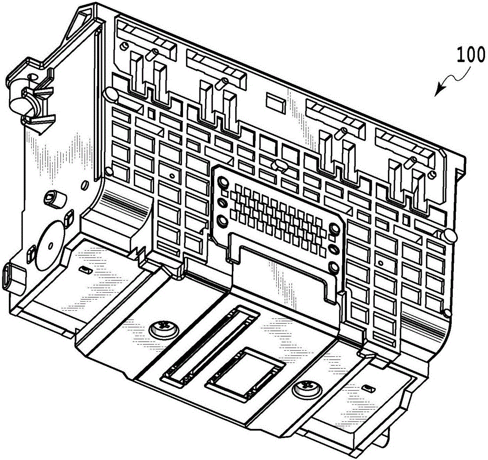
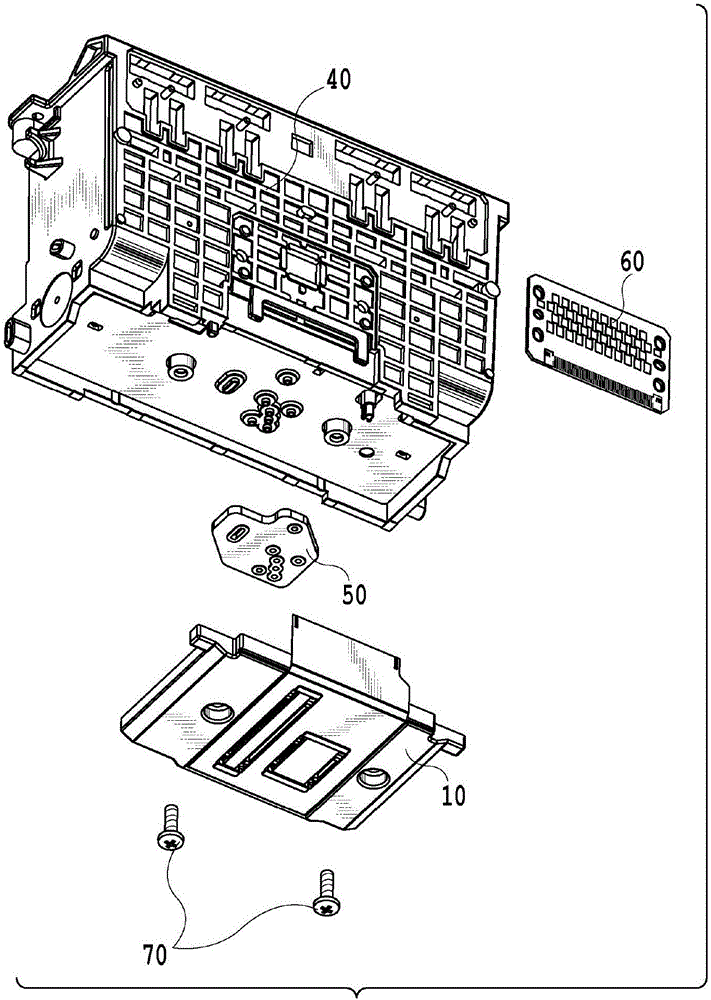
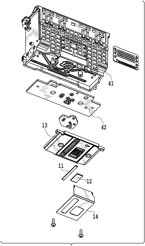
[0031] figure 1 is a schematic diagram showing the liquid ejection head of the first embodiment, figure 2 and image 3 It is an exploded view of the liquid ejection head. The liquid ejection head 100 has a printing element unit 10 , a flow path unit 40 , an elastic member 50 , an electric substrate 60 and screws 70 . The printing element unit 10 has printing element substrates 11 and 12 , a plate-shaped supporting member (first supporting member) 13 and an electric wiring substrate 14 , and the flow path unit 40 (second supporting member) has a casing 41 and a flow path plate 42 .

[0032] The flow path unit 40 has a flow path plate 42 fixed to the housing 41 by ultrasonic welding to form a liquid supply path for guiding liquid from an ink cartridge for storage (not shown) to a liquid introduction port. The housing 41 and the flow path plate 42 are formed of resin...

no. 2 approach

[0045] A second embodiment of the present invention will be described below by referring to the drawings. Since the basic configuration of the present embodiment is the same as that of the first embodiment, only the characteristic configuration will be described below.

[0046] Figure 10 It is a figure for demonstrating the printing element unit of 2nd Embodiment. Since the configurations other than the printing element unit are the same as those of the liquid ejection head of the first embodiment, description will be omitted. In the support member 13 , recesses 23 for accommodating the printing element substrates 11 and 12 in the thickness direction of the support member 13 are provided. The outer peripheries of the printing element substrates 11 and 12 (or at least a part of the printing element substrates 11 and 12 ) engaging and fixed to the concave portion 23 of the supporting member 13 are sealed with a sealing material 24 . Since the supporting member 13 is formed o...


PUM


Abstract

The invention provides a liquid ejection head and a manufacturing method of the liquid ejection head. The liquid ejection head with high environmental reliability which suppresses a crack of a Si substrate and peeling-off of an ejection port forming member by relaxing a residual stress in a printing element substrate and a manufacturing method of a liquid ejection head are provided. For that purpose, after the printing element substrate is bonded and fixed to a support member, the support member is screwed and fixed through an elastic member.

Description

technical field [0001] The present invention relates to a liquid ejection head mounted on a liquid ejection device that performs a printing operation by ejecting printing liquid such as ink, and a method of manufacturing the liquid ejection head. Background technique [0002] Japanese Patent Application Laid-Open No. 2002-19146 discloses a liquid ejection head in which a joint sealing member is sandwiched between a flow path unit in which a liquid supply path is formed and a supporting member supporting a printing element substrate, and they are screwed together. Engaged in pressure contact with each other so that the liquid does not leak. The printing element substrate is formed of a silicon wafer, and the material of the supporting member is alumina or the like having a linear expansion coefficient equal to that of the printing element substrate. [0003] By making the coefficient of linear expansion of the printing element substrate and the coefficient of linear expansio...

Claims


Application Information

Patent Timeline
Patent Type & Authority Applications(China)
IPC IPC(8): B41J2/14
CPCB41J2/14B41J2/16B41J2/1623B41J2/1626B41J2/1635B41J2002/14362Y10T29/49403
Inventor 工藤清光木村了黑田伦嗣辻内直子
Owner CANON KK
Why Eureka
Try Eureka