
A vertically-opening ice breaking high-voltage isolation switch

A high-voltage isolation switch and crampon technology, which is applied to switches with movable electrical contacts, etc., can solve the problems of hidden safety hazards, long ice melting time, and inability to achieve ice breaking, and achieves fast ice breaking, reliable operation, and simple structure. reasonable effect

Inactive Publication Date: 2016-01-20
SOUTHWEST JIAOTONG UNIV
View PDF6 Cites 0 Cited by
  • Summary
  • Abstract
  • Description
  • Claims
  • Application Information

AI Technical Summary

Problems solved by technology

At present, one measure to solve the problem of normal operation of the high-voltage isolating switch under ice-covered conditions is to melt ice, such as CN201120308342.1, CN201220115423, CN201210507343, CN201420554736.9, etc., the ice is melted by direct current, but the ice-melting time is relatively long. And there are certain security risks
The high-voltage isolating switch with non-melting measures uses the movement of the moving contact driven by the operating mechanism to achieve forced ice breaking. Due to the power of the operating mechanism, the rigidity of the operating mechanism, and the strength and stiffness of the conductive device, when the ice is too thick Unable to achieve ice breaking effect
The current vertically open high-voltage isolating switch can basically meet the ice breaking requirements under the condition of 10mm of ice covering, but cannot realize the closing and breaking of ice under the condition of 20mm of ice covering

Method used


Image

  • A vertically-opening ice breaking high-voltage isolation switch
  • A vertically-opening ice breaking high-voltage isolation switch
  • A vertically-opening ice breaking high-voltage isolation switch

Examples


Embodiment Construction

[0016] The present invention will be further described in detail below in conjunction with the accompanying drawings.

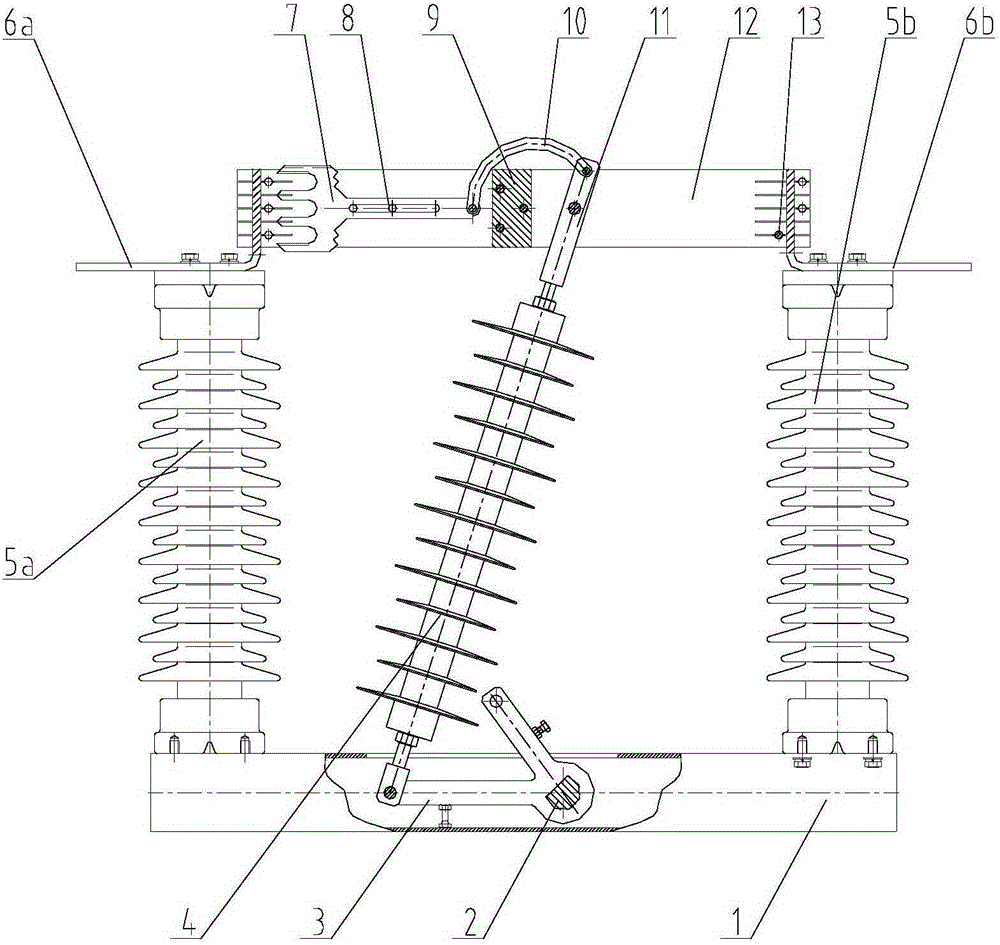
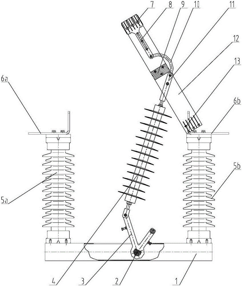
[0017] A structure for vertically opening the ice-breaking high-voltage isolating switch such as figure 1 As shown, two support insulators (5a and 5b) are fixed on the chassis 1, and conductive static contacts (6a and 6b) are fixed on the two support insulators. One end of the conductive arm 12 is hinged to a conductive The static contact 6b has a spacer 9 between the two conductive arms. The crank arm shaft 2 is installed on the chassis 1, the crank arm 3 is fixed on the crank arm shaft 2, one end of the operating insulator 4 is hinged to the crank arm 3, the other end is fixed to one end of the operating pull rod 11, and the other end of the operating pull rod 11 is hinged to the conductive arm 12.

[0018] Crampons 7 are arranged in the inner movable contact area of ​​the conductive arm 12, and the crampons move longitudinally along the conductive arm. ...


PUM


Abstract

The invention discloses a vertically-opening ice breaking high-voltage isolation switch. The upper portion of an operation pull bar (11) is in hinged connection with one end of an ice breaking connecting rod (10). The other end of the ice breaking connecting rod (10) is in hinged connection with an ice breaking claw (7). The ice breaking claw (7) which can slide longitudinally along the surface of a conductive arm moving contact is arranged on the inner side of a moving contact area of a conductive arm (12). The tail portion of the ice breaking claw (7) is in hinged connection with the ice breaking connecting rod (10). The other end of the ice breaking connecting rod (10) is in hinged connection with the operation pull bar (11). According to the invention, through utilization of characteristics of relatively low shearing intensity of ice, motions of the moving contact pull bar simultaneously drives the motions of an ice breaking mechanism so as to realize ice breaking of the moving contact in a closing process; then the moving contact which is without ice carries out ice breaking on the static contact under working of the operation mechanism. The structure is simple and reasonable; the working is reliable; and requirements of rapid ice breaking can be satisfied.

Description

technical field [0001] The invention belongs to the field of high-voltage electrical equipment, in particular to a high-voltage isolating switch with a mechanical ice-breaking function. Background technique [0002] The national standard GB1985-2004 "High Voltage AC Isolating Switches and Grounding Switches" stipulates the operating requirements for ice-breaking operations under severe freezing conditions, that is, the opening and closing tests under the conditions of level 10 (10mm ice coating) and level 20 (ice coating 20mm). At present, one measure to solve the problem of normal operation of the high-voltage isolating switch under ice-covered conditions is to melt ice, such as CN201120308342.1, CN201220115423, CN201210507343, CN201420554736.9, etc., the ice is melted by direct current, but the ice-melting time is relatively long. And there are certain security risks. The high-voltage isolating switch with non-melting measures uses the movement of the moving contact drive...

Claims


Application Information

Patent Timeline
IPC IPC(8): H01H31/30
CPCH01H31/30
Inventor 邓斌王国志柯坚吴文海于兰英
Owner SOUTHWEST JIAOTONG UNIV
Learn More