A Design Method for Aspheric Panoramic Reflector

A mirror, aspheric technology, used in mirrors, optics, instruments, etc., to improve imaging quality and eliminate distortion

Inactive Publication Date: 2018-06-22
HEILONGJIANG UNIVERSITY OF SCIENCE AND TECHNOLOGY
View PDF3 Cites 0 Cited by
  • Summary
  • Abstract
  • Description
  • Claims
  • Application Information

AI Technical Summary

Problems solved by technology

However, in the current panoramic system, there is a large image distortion in the panorama image expansion. Many methods have been proposed to reduce and eliminate this distortion. Improving the surface profile of the mirror is a relatively direct and effective method, which can greatly improve the mirror image. linearity of expansion

Method used


Image

  • A Design Method for Aspheric Panoramic Reflector
  • A Design Method for Aspheric Panoramic Reflector
  • A Design Method for Aspheric Panoramic Reflector

Examples


Embodiment 1

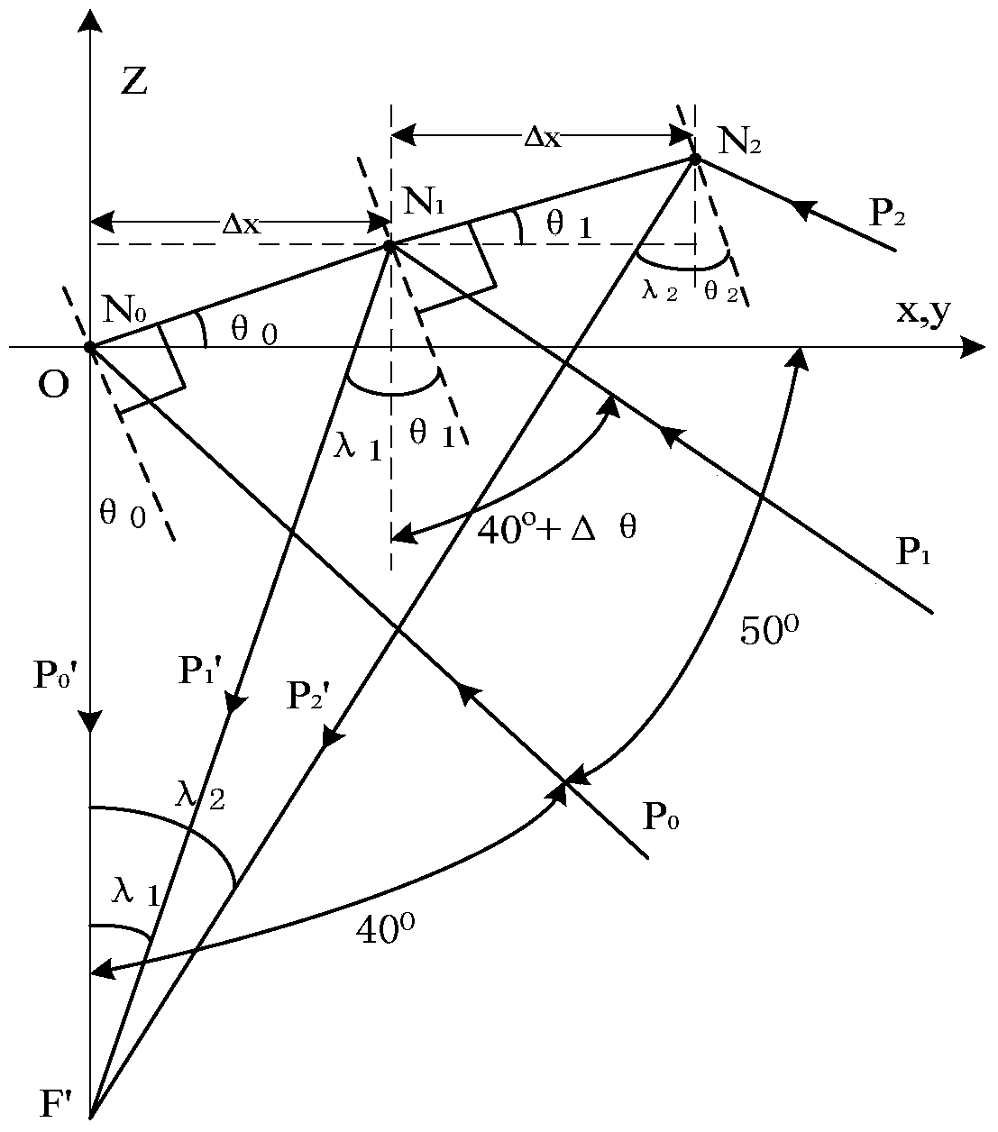
[0010] A method for designing aspheric mirrors for omni-directional vision systems. Determine the three parameters of the mirror’s diameter, thickness and maximum incident angle. According to the maximum incident angle and the required processing accuracy, select the appropriate number of sampling points. The number of points is subdivided into diameter and thickness. For a cluster of coaxial hyperbolas with the same focal length and linearly increasing real axis length, horizontally intercept the curve segments and perform finite element splicing to obtain a surface curve that meets certain requirements. Substitute it into the iterative formula to obtain samples The coordinates of the points, the sampling points generated by the iterative equation are fitted to the contour curve equation of the aspheric surface and converted into the optical equation recognized by ZEMAX.

[0011] The space angle between two adjacent incident rays of the specified curved surface is Δθ=(β-α) / m, tha...


PUM


Abstract

The invention discloses a novel aspheric reflector design method for an omnidirectional vision system. The method is characterized by comprising steps: the diameter, the thickness and the maximum incidence angle of the reflector are determined, a proper sampling point number is selected according to the maximum incidence angle and required processing precision, the diameter and the thickness are subdivided according to the sampling point number, as for a cluster of coaxial hyperbolic curves with the same focus and with real axis lengths increased linearly, curve segments are intercepted horizontally for finite element splicing to obtain a surface-type curve meeting certain requirements, an iterative formula is substituted, coordinates of the sampling points are obtained, the sampling points generated by an iterative equation are used for fitting an aspheric contour curve equation, and the equation is converted into ZMAX recognition optical equation.

Description

Technical field [0001] The invention belongs to the field of omni-directional vision processing, and particularly relates to a design method of an aspheric panoramic mirror. Background technique [0002] With the continuous improvement of the panoramic vision system, the panoramic vision technology has had preliminary applications in the field of vision and optics. In indoor and outdoor environments, panoramic vision is gradually being used in fields such as surveillance and remote reality. Due to its 360-degree viewing angle range, the most direct application of the panoramic vision system in the outdoor environment is in the field of surveillance. Cameras based on omni-directional vision sensors have very prominent advantages. They have a wide field of view (360 degrees) and can compress the information in a hemispherical field of view into an image. An image has a larger amount of information, and any point in the panoramic image Corresponds to a certain point in the surveil...

Claims


Application Information

Patent Timeline
Patent Type & Authority Patents(China)
IPC IPC(8): G02B5/10G02B27/00
CPCG02B5/10G02B27/0012
Inventor 梁燕华赵振民姜艳秋蔡成涛徐益民祁红岩李忠勤
Owner HEILONGJIANG UNIVERSITY OF SCIENCE AND TECHNOLOGY
Why Eureka
Try Eureka