
Cam diaphragm vacuum valve for pressure casting

A technology of vacuum valve and diaphragm, which is applied in the direction of valve details, valve device, valve operation/release device, etc. It can solve the problems of large thread stroke, inconvenient vacuum valve to open and close quickly, and slow opening and closing speed, so as to achieve good airtightness performance, easy to manufacture and install, and easy to replace

Inactive Publication Date: 2016-01-20
CHONGQING YINGRUISHENG DIE CASTING
View PDF0 Cites 0 Cited by
  • Summary
  • Abstract
  • Description
  • Claims
  • Application Information

AI Technical Summary

Problems solved by technology

However, the thread rotation is used to open and close the valve body, the stroke of the thread is large, and the opening and closing speed is slow, which is not convenient for the rapid opening and closing of the vacuum valve.

Method used


Image

  • Cam diaphragm vacuum valve for pressure casting

Examples


Embodiment Construction

[0012] The present invention will be described in further detail below by means of specific embodiments:

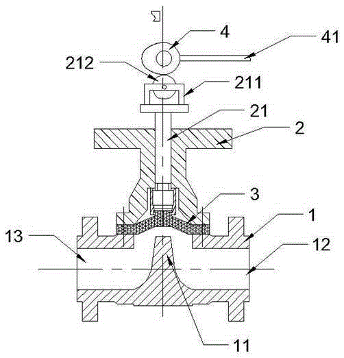
[0013] The reference signs in the accompanying drawings include: lower valve body 1, valve core 11, air inlet 12, air outlet 13, upper valve body 2, valve stem 21, support frame 211, pulley 212, diaphragm 3, cam 4, handle41.

[0014] The embodiment is basically as attached figure 1 Shown:

[0015] The cam diaphragm vacuum valve for die-casting in this solution includes a diaphragm 3 and a valve stem 21, the valve stem 21 is sleeved in the upper valve body 2, the lower end of the valve stem 21 is connected to the diaphragm 3, the valve core 11 is located below the diaphragm 3, and the valve core 11 It is integrally formed with the lower valve body 1. The two sides of the valve core 11 are respectively provided with an air inlet 12 and an air outlet 13. The air inlet 12 and the air outlet 13 are connected through the gap between the valve core 11 and the diaphragm 3. . ...


PUM


Abstract

The invention relates to the technical field of diaphragm cutoff devices and discloses a cam diaphragm vacuum valve for pressure casting. The cam diaphragm vacuum valve for pressure casting comprises a valve body, a diaphragm and a valve rod. The valve rod is sleeved with the valve body. The lower end of the valve rod is connected with the diaphragm. A valve element is arranged below the diaphragm. An air inlet and an air outlet are formed in the two sides of the valve element respectively and communicated with each other through a gap between the valve element and the diaphragm. A pulley is hinged to the upper end of the valve rod. A cam matched with the pulley is arranged above the pulley and provided with a handle. By the adoption of the scheme, cam rotating downward pressing operation is used for replacing screw rotating downward pressing operation, the valve is quicker to open and close, a response is made quickly, control is more convenient and quicker, and pressure casting efficiency is effectively improved.

Description

technical field [0001] The invention relates to the technical field of diaphragm cutting devices. Background technique [0002] The vacuum die-casting method is to extract the gas in the cavity, and the molten metal fills the cavity in a vacuum state, so less gas is involved, the mechanical properties of the casting are high, and the vacuum die-casting inherits and maintains the advantages of the ordinary die-casting method. The vacuum degree is in the range of 52-82KPa (380-600mmHg), which can be obtained by mechanical pumps, and the vacuum degree requirements for thin-walled and complex die-casting parts will be higher. Vacuum die-casting has the following advantages: vacuum die-casting method can eliminate or reduce the pores inside die-casting parts, improve the mechanical properties and surface quality of die-casting parts, and improve the coating performance; vacuum die-casting method greatly reduces the back pressure of the cavity and can use lower For alloys with po...

Claims


Application Information

Patent Timeline
Patent Type & Authority Applications(China)
IPC IPC(8): F16K31/524
CPCF16K31/52491
Inventor 王燕
Owner CHONGQING YINGRUISHENG DIE CASTING
Learn More