Cassette-type nozzle exchange unit and replacement system therefor
A box-type, nozzle table technology, applied in the direction of electrical components, electrical components, conveyor objects, etc., can solve the problems of longer moving distance, increased occupation area, and reduced operation efficiency of nozzle replacement, so as to reduce replacement frequency, interference avoidance, space saving effect
- Summary
- Abstract
- Description
- Claims
- Application Information
AI Technical Summary
Problems solved by technology
Method used
Image


Examples
Embodiment 1
[0039] based on Figure 1 to Figure 8 Example 1 of the present invention will be described.
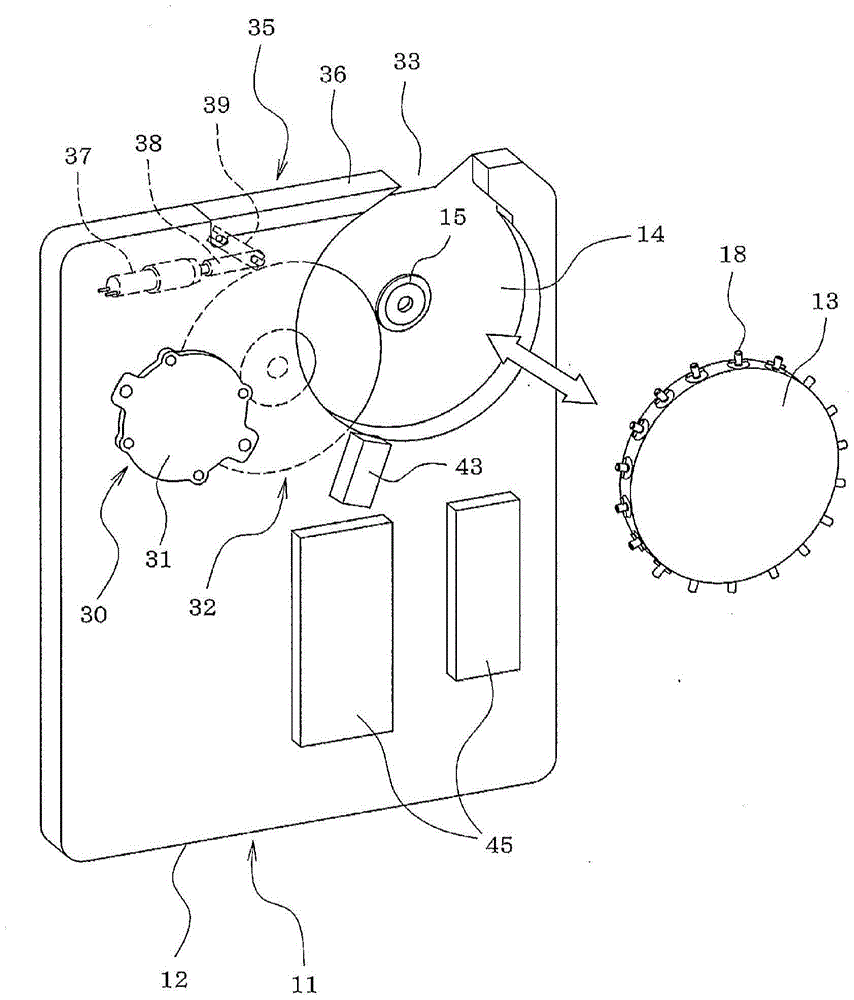
[0040] First, based on figure 1 and figure 2 The configuration of the cartridge nozzle replacement unit 11 will be described.
[0041] The cartridge case 12 of the cartridge nozzle replacement unit 11 is formed of a transparent or opaque plastic plate, metal plate, or the like, and the side surface portion (cover) of the cartridge case 12 can be opened and closed. The cartridge housing 12 is provided with a circular recess-shaped suction nozzle station filling part 14 in which a disc-shaped rotary suction nozzle station 13 is filled in a detachable (replaceable) manner, and a drive shaft 15 (refer to figure 2 ) is installed in the center of the nozzle table loading part 14 in the horizontal direction, and the center part of the rotary nozzle table 13 is connected to the drive shaft 15 in a manner capable of transmitting rotation and detachable.
[0042] Will be used for the moun...
Embodiment 2
[0088] In the first embodiment described above, the reader 43 for reading the nozzle ID from the nozzle identification information recording part 42 of the nozzle 18 in the cartridge nozzle replacement unit 11 is arranged inside the cartridge case 12, but Figure 9 In the cartridge-type nozzle replacement unit 11 according to the second embodiment of the present invention shown, a device for reading the nozzle ID from the nozzle identification information recording part 42 of the nozzle 18 is disposed near the nozzle replacement port 33 of the cartridge case 12. Reader 93 (identification information reading unit), and by this reader 93 from the suction nozzle 18 that is held on the mounting head 58 of component mounting machine 55 via suction nozzle replacement port 33, for example two previous suction nozzles 18 The nozzle identification information recording unit 42 reads the nozzle ID. Other structures are the same as the above-mentioned embodiment 1.
[0089] Also in the ...
Embodiment 3
[0092] Next, use Figure 10 to Figure 13 Embodiment 3 of the present invention will be described. However, the same reference numerals are assigned to the parts that are substantially the same as those in the first embodiment described above, and the description thereof will be omitted or simplified, and the different parts will be mainly described.
[0093] The third embodiment differs from the first embodiment above in that the structure for holding the suction nozzle 18 on the nozzle holder 94 of the rotary nozzle table 13 is a spring-based engagement method. The seat housing 95 of the nozzle holder 94 of the third embodiment is radially fixed to the outer peripheral part of the rotary nozzle table 13, and the nozzle pressing part cylinder part 96 and the clamping cylinder part 97 are provided on the housing shell both inside and outside. Inside the body 95. The height of the upper end of the inner nozzle pressing part cylindrical part 96 is lower than the height of the u...
PUM
 Abstract
Description
Claims
Application Information
 - R&D
- Intellectual Property
- Life Sciences
- Materials
- Tech Scout
- Unparalleled Data Quality
- Higher Quality Content
- 60% Fewer Hallucinations
Browse by: Latest US Patents, China's latest patents, Technical Efficacy Thesaurus, Application Domain, Technology Topic, Popular Technical Reports.
© 2025 PatSnap. All rights reserved.Legal|Privacy policy|Modern Slavery Act Transparency Statement|Sitemap|About US| Contact US: help@patsnap.com