
A signal acquisition control circuit

A control circuit and signal acquisition technology, which is applied in the direction of instruments, measuring devices, and wave/particle radiation, can solve the problem of small signal acquisition range, achieve the effect of improving the range of signal acquisition, increasing the test distance, and improving the measurement range

Active Publication Date: 2018-11-30
WEIHAI BEIYANG PHOTOELECTRIC INFORMATION TECH
View PDF6 Cites 0 Cited by
  • Summary
  • Abstract
  • Description
  • Claims
  • Application Information

AI Technical Summary

Problems solved by technology

[0006] The present invention provides a signal acquisition control circuit with a large signal acquisition range in order to solve the technical problem that the signal acquisition range of the ADC is small during the processing of Rayleigh optical signals by the existing optical fiber vibration intrusion monitoring system

Method used


Image

  • A signal acquisition control circuit
  • A signal acquisition control circuit
  • A signal acquisition control circuit

Examples


Embodiment Construction

[0021] Referring to the accompanying drawings, the present invention will be further described in detail with specific embodiments.

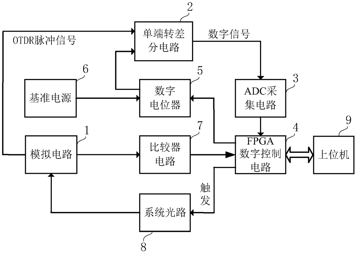
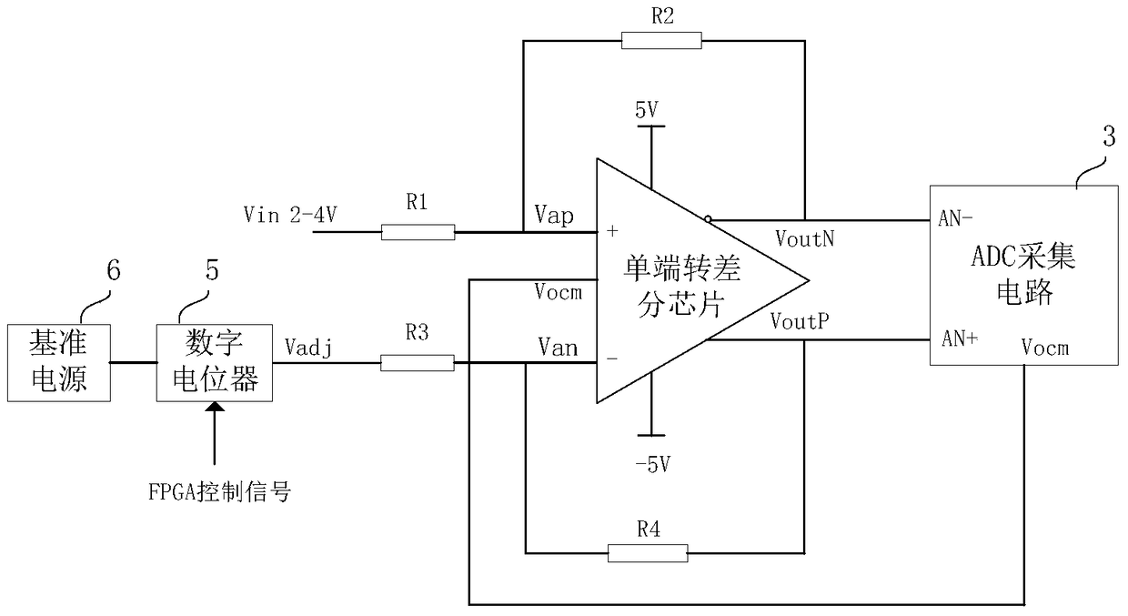
[0022] Such as figure 1 As shown, the system optical path 8 is connected to the FPGA digital control circuit 4, the analog circuit 1 is connected to the system optical path 8, the host computer 9 is connected to the FPGA digital control circuit 4, and the non-inverting end of the comparator circuit 7 is connected to the output end of the analog circuit 1, The inverting terminal of the comparator circuit 7 is connected to a 2V reference voltage, and the output terminal of the comparator circuit 7 is connected to the FPGA digital control circuit 4; the reference power supply 6 is connected to the input terminal of the digital potentiometer 5, and the control terminal of the digital potentiometer 5 is connected to the FPGA digital control circuit The control circuit 4 is connected, the output terminal of the digital potentiometer 5 is connected to ...


PUM


Abstract

The invention relates to a signal collection control circuit, which is used for solving the technical problem that an existing optical fiber vibration intrusion monitoring system has a small collection range on ADC signals in a processing procedure of Rayleigh optical signals. The signal collection control circuit comprises an FPGA digital control circuit, an ADC collection circuit, a single-ended to differential circuit, a digital potentiometer and a comparator circuit, wherein an output end of the comparator circuit is connected with the FPGA digital control circuit, a control end of the digital potentiometer is connected with the FPGA digital control circuit, the output end of the digital potentiometer is connected with an inverted end of the single-ended to differential circuit, the output end of the single-ended to differential circuit is connected with an input end of the ADC collection circuit, and the output end of the ADC collection circuit is connected with the FPGA digital control circuit. The signal collection control circuit provided by the invention is widely applied to optical fiber vibration intrusion monitoring systems.

Description

technical field [0001] The invention relates to an ADC control circuit, in particular to a signal acquisition control circuit. Background technique [0002] As a new type of perimeter intrusion monitoring system, the fiber optic vibration intrusion monitoring system can perceive external vibration information, and is resistant to electromagnetic interference and not affected by harsh environments. It is mainly used for intrusion monitoring of pipelines, stations, and important buildings. The optical fiber vibration intrusion monitoring system has obvious advantages in terms of measurement distance, service life, safety, reliability, concealment, detection accuracy and alarm efficiency. The fiber optic vibration intrusion monitoring system is flexible, simple, and low in cost, and has become the product of choice for a new generation of security monitoring. [0003] Currently commonly used optical fiber vibration intrusion monitoring systems are often based on Principle or...

Claims


Application Information

Patent Timeline
Patent Type & Authority Patents(China)
IPC IPC(8): H03M1/12G01H9/00
Inventor 张凯史振国王建强夏俊玲张永臣乔秋晓刘伟何春芝李德和于娟
Owner WEIHAI BEIYANG PHOTOELECTRIC INFORMATION TECH
Learn More