
Live monitoring method and system for high-voltage direct current transmission lines

A high-voltage DC, monitoring system technology, applied in circuit devices, electrical components, emergency power supply arrangements, etc., can solve the problems of DC engineering line maintenance, monitoring and management difficulties, theft of line facilities and equipment, etc., to achieve stable and more reliable monitoring information , The effect of preventing theft and saving manpower input

Inactive Publication Date: 2020-06-16
CHINA ENERGY ENG GRP GUANGDONG ELECTRIC POWER DESIGN INST CO LTD
View PDF5 Cites 0 Cited by
  • Summary
  • Abstract
  • Description
  • Claims
  • Application Information

AI Technical Summary

Problems solved by technology

[0006] One of the purposes of the present invention is to provide a live monitoring method for high-voltage direct current transmission lines in order to solve the problems of difficulties in line maintenance, monitoring and management during the rest period of DC projects, and the problems that line facilities and equipment are easily stolen
[0007] The second purpose of the present invention is to provide a live monitoring system for high-voltage direct current transmission lines in order to solve the problems of difficulty in line maintenance, monitoring and management during the rest period of the DC project, and the problems that line facilities and equipment are easy to be stolen

Method used


Image

  • Live monitoring method and system for high-voltage direct current transmission lines
  • Live monitoring method and system for high-voltage direct current transmission lines

Examples


specific Embodiment 1

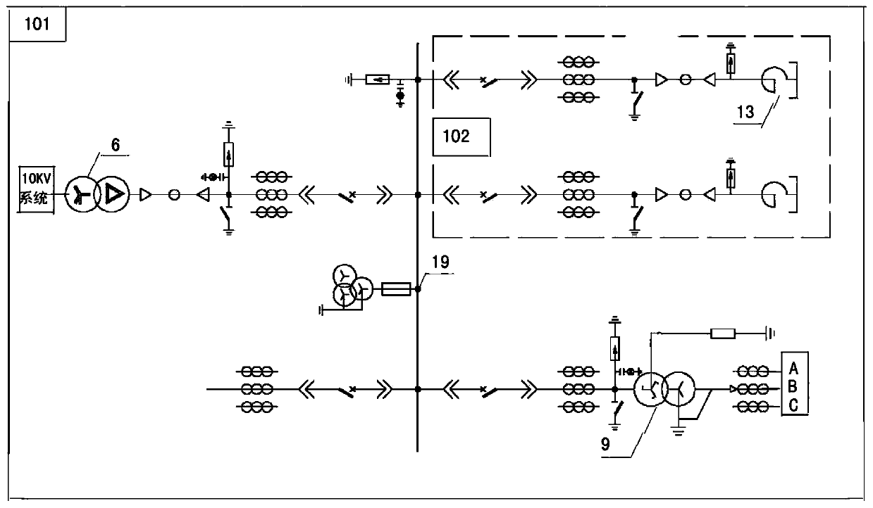
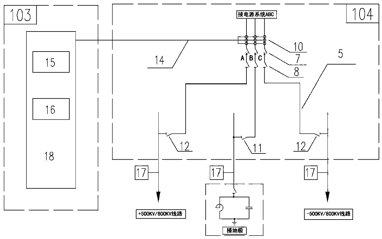
[0031] refer to figure 1 , figure 2 , the live monitoring system of the high-voltage DC transmission line involved in this implementation includes a power supply device 101, a reactive power compensation device 102, a monitoring and protection device 103, and an isolation device 104. The power supply device 101 includes a 10kV / 35kV step-up transformer, a 35kV circuit breaker and 35kV isolation transformer, the input end of the power supply device 101 is connected to the 10kV system, and the output end is connected to the input end of the isolation device 104; the reactive power compensation device 102 is set on the 35kV bus of the power supply device 101 to form capacitive reactive power compensation for the no-load line Structure; the monitoring protection device 103 has several detection signal input terminals and at least one control output terminal, and the detection signal input terminal of the monitoring protection device 103 is connected to the equipment along the line...


PUM


Abstract

The invention relates to a live monitoring method and a system for a high-voltage DC power transmission line. The method is characterized by comprising steps: 1) a line live monitoring system in the case of outage is built, 35kV voltage is loaded to the original power transmission line in the case of outage, the power transmission line can still operate lively in the outage period, the power transmission line can play a role of theft prevention, and the system after AC voltage loaded can operate stably in a no-load mode; 2) when a fault or an accident happens to the power transmission line, on one hand, voltage and current measurement data of the power transmission line are analyzed via a fault location system for fault location, and on the other hand, a protection tripping system of the power transmission line is started, the line is tripped, and the power transmission line is protected; and 3) in the case of outage of the power transmission line, a power supply for an AC station in a converter station is used for charging the positive electrode, the negative electrode and the grounding electrode of the power transmission line. Through building the line live monitoring system in the case of outage, the line can be monitored in real time, line facilities can be prevented from being stolen, overhaul and maintenance are convenient, and the management efficiency is high.

Description

technical field [0001] The invention relates to a live monitoring method and system for a high-voltage direct current transmission line. The utility model belongs to the technical field of high-voltage line monitoring equipment for direct current engineering. Background technique [0002] DC projects are usually used in long-distance, high-power transmission situations. In China, it is more common in my country to directly send electric energy from power centers in the west of China, such as large hydropower stations or large coal energy base power plants, to energy consumption centers in the east. When the electric energy of the power center is at a low ebb, such as when the hydropower station is in the dry season or the water shortage period, the DC converter station may stop supplying power during the rest period of the power transmission cycle. For example, in the upcoming multi-country DC interconnection project in Central Asia, the DC converter station will work for 5...

Claims


Application Information

Patent Timeline
Patent Type & Authority Patents(China)
IPC IPC(8): H02J13/00H02J9/00
Inventor 岳云峰简翔浩王宏斌周敏贺艳芝孔志达丁伟
Owner CHINA ENERGY ENG GRP GUANGDONG ELECTRIC POWER DESIGN INST CO LTD
Learn More