Eureka AIR delivers breakthrough ideas for toughest innovation challenges, trusted by R&D personnel around the world.

Anti-flowing backwards protection circuit

A protection circuit and anti-backflow technology, applied in emergency protection circuit devices, electrical components, etc., can solve the problems of difficult heat dissipation and high power consumption

Active Publication Date: 2016-01-13
SICHUAN HUIYUAN OPTICAL COMM CO LTD
View PDF3 Cites 12 Cited by
  • Summary
  • Abstract
  • Description
  • Claims
  • Application Information

AI Technical Summary

Problems solved by technology

[0004] In view of this, the present invention provides an anti-backfeed protection circuit to improve the technical problems of large power consumption and difficult heat dissipation when diodes are used to achieve anti-backfeed in the prior art

Method used


Image

  • Anti-flowing backwards protection circuit
  • Anti-flowing backwards protection circuit
  • Anti-flowing backwards protection circuit

Examples


Embodiment Construction

[0017] The present invention will be described in further detail below through specific implementation examples and in conjunction with the accompanying drawings.

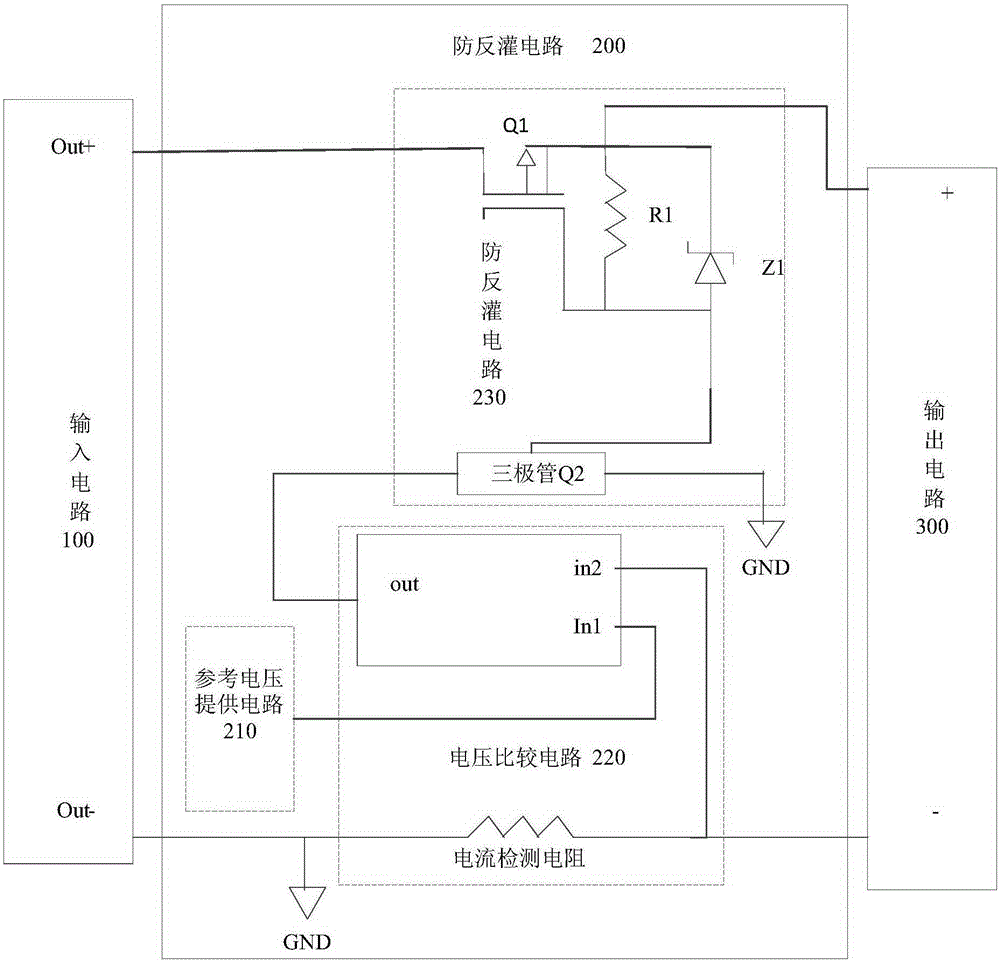
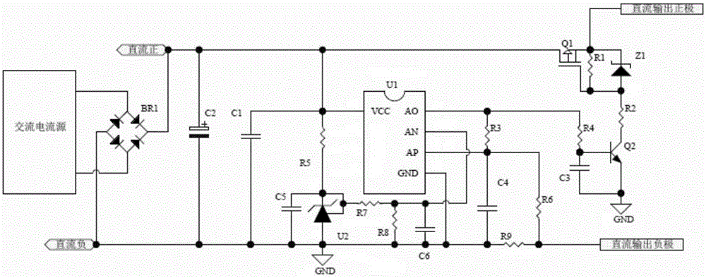
[0018] refer to figure 2 , the anti-backfeed protection circuit 200 provided by the present invention is electrically connected between an input circuit 100 and an output circuit 300 . The anti-backfeed protection circuit 200 includes: a reference voltage supply circuit 210 , a voltage comparison circuit 220 and an anti-backfeed control circuit 230 . The voltage comparison circuit 220 includes a current detection resistor. The output end of the reference voltage supply circuit 210 is connected to the first input end of the voltage comparison circuit 220 . The negative pole of the input circuit 100 is connected to the negative pole of the output circuit 300 via the current detection resistor, and a feedback voltage formed on the current detection resistor acts on the second input terminal of the voltage compariso...


PUM


Abstract

The invention provides an anti-flowing backwards protection circuit, which is electrically connected between an input circuit and an output circuit. The anti-flowing backwards protection circuit comprises a reference voltage providing circuit, a voltage comparing circuit and an anti-flowing backwards circuit, wherein the voltage comparing circuit comprises a current detection resistor; the output end of the reference voltage providing circuit is connected with the first input end of the voltage comparing circuit; the negative electrode of the input circuit is connected with the negative electrode of the output circuit via the current detection resistor; feedback voltage is formed on the current detection resistor to act on the second input end of the voltage comparing circuit; and the anti-flowing backwards circuit comprises a P channel MOSFET. Through comparing the reference voltage and the feedback voltage by the voltage comparing circuit, the working state of the P channel MOSFET is controlled through the output end of the voltage comparing circuit, backward flowing current can be prevented from entering the input circuit from the output circuit, and the technical problems of large power consumption and much cooling when a diode is adopted in the prior art to realize backward flowing prevention can be solved.

Description

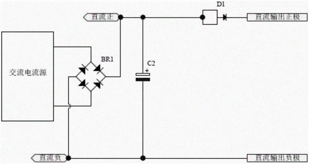
technical field [0001] The invention relates to the technical field of circuit protection, in particular to an anti-backfeed protection circuit. Background technique [0002] The anti-backfeed protection circuit is often used to prevent the power supply from being damaged by the current backfeed at the output terminal. The anti-backfeed control circuit of the DC output in the prior art realizes the anti-backfeed through a diode. The circuit is as follows: figure 1 , the AC current source rectifies the AC to DC through the rectifier bridge BR1, the DC positive pole of the rectifier bridge BR1 is connected to the positive pole of C2, the negative pole of DC is connected to the negative pole of C2, and C2 is used for energy storage and filtering. The positive pole of the direct current is connected to the positive pole of the diode D1, and the negative pole of the diode D1 is connected to the positive pole of the direct current output. The DC output negative pole is directly c...

Claims


Application Information

Patent Timeline
Patent Type & Authority Applications(China)
IPC IPC(8): H02H11/00
Inventor 李绍飞宋昌林陈方春
Owner SICHUAN HUIYUAN OPTICAL COMM CO LTD
Why Eureka
Eureka Blog
Learn More