Eureka AIR delivers breakthrough ideas for toughest innovation challenges, trusted by R&D personnel around the world.

Image adjustment method, device and system for horizontally installed photoelectric pod

A photoelectric pod and image adjustment technology, applied in the field of imaging, can solve the problems of image viewing angle deviation and inconvenience, and achieve the effect of convenient observation

Active Publication Date: 2019-07-09
BEIJING GEMSTONE PRECISION INSTR TECHCO
View PDF3 Cites 0 Cited by
  • Summary
  • Abstract
  • Description
  • Claims
  • Application Information

AI Technical Summary

Problems solved by technology

Therefore, the reference axes of the hoisted photoelectric pod and the horizontal photoelectric pod are perpendicular to each other. When the photoelectric pod captures the image directly below the carrier aircraft, the image angles formed by the horizontal and hoisted photoelectric pods are consistent. Yes, but once the image captured by the photoelectric pod deviates from the directly below the carrier aircraft, due to the inconsistency between the angles of view of the horizontally mounted photoelectric pod and the hoisted photoelectric pod, the angle of view of the captured image is also greatly deviated
In general, the hoisted photoelectric pod is similar to the image presented in the eyes of a person looking directly to the left and right, while the photoelectric pod installed in the horizontal position is similar to the image presented in the eyes of a person looking directly to the left and right. The image has a large deviation, and the observer needs to convert the corresponding relationship between the image and the direction in the brain before he can recognize it, which is very inconvenient for the observer

Method used


Image

  • Image adjustment method, device and system for horizontally installed photoelectric pod
  • Image adjustment method, device and system for horizontally installed photoelectric pod
  • Image adjustment method, device and system for horizontally installed photoelectric pod

Examples


Embodiment Construction

[0064] The following will clearly and completely describe the technical solutions in the embodiments of the present invention with reference to the accompanying drawings in the embodiments of the present invention. Obviously, the described embodiments are only some, not all, embodiments of the present invention. The components of the embodiments of the invention generally described and illustrated in the figures herein may be arranged and designed in a variety of different configurations. Accordingly, the following detailed description of the embodiments of the invention provided in the accompanying drawings is not intended to limit the scope of the claimed invention, but merely represents selected embodiments of the invention. Based on the embodiments of the present invention, all other embodiments obtained by those skilled in the art without making creative efforts belong to the protection scope of the present invention.

[0065] Due to the different assembly methods, the pi...


PUM


Abstract

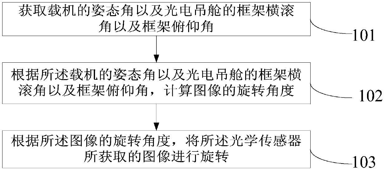
The present invention relates to the technical field of imaging, in particular to a horizontally mounted photoelectric pod image adjustment method, apparatus and system. The method comprises: acquiring attitude angles of a carrier and a frame roll angle and a frame pitch angle of a photoelectric pod, wherein the attitude angles include a carrier azimuth, a carrier pitch angle and a carrier roll angle; according to the attitude angles of the carrier and the frame roll angle and the frame pitch angle of the photoelectric pod, calculating a rotational angle of an image; and according to the rotational angle, rotating the image obtained by an optical sensor. According to the image adjustment method, apparatus and system provided by the present invention, the rotational angle of the image is calculated, and according to the rotational angle, the image obtained by the optical sensor is rotated; and the rotated image is an image obtained when a photoelectric pod scans a same object, so that observation habits of human eyes are better fitted, observers are not required to perform conversion on a correspondence between the image and a direction, and the observation is more convenient.

Description

technical field [0001] The present invention relates to the field of imaging technology, in particular to an image adjustment method, device and system for a horizontal photoelectric pod. Background technique [0002] The pod refers to a streamlined nacelle section that is installed with certain airborne equipment or weapons and is hung under the fuselage or wing. The photoelectric pod is a type of pod, usually equipped with optical sensors such as forward-looking infrared cameras, TV cameras, and laser pointers / rangefinders. According to the functions, there are currently two types of onboard navigation pods and targeting pods. With the continuous development of precision-guided weapon technology, the aviation optoelectronic pod has become an important part of the precision strike system of fighter jets. It isolates the influence of attitude changes and mechanical vibrations of the carrier aircraft on the pointing of the optical sensor. At the same time, it uses the optic...

Claims


Application Information

Patent Timeline
Patent Type & Authority Patents(China)
IPC IPC(8): G06T3/60
CPCG06T3/604
Inventor 付昱
Owner BEIJING GEMSTONE PRECISION INSTR TECHCO
Why Eureka
Eureka Blog
Learn More