
Stereoscopic endoscope electronic imaging optical system

A technology of stereoscopic endoscope and optical system, which is applied in the design of electronic imaging optical system of stereoscopic endoscope with large field of view, and in the field of small distortion. It can solve the problems of large spherical radius, difficult processing, and inability to correct aberrations. The effect of working length, low processing cost, and fewer lenses

Active Publication Date: 2016-01-13
TIANJIN UNIV
View PDF3 Cites 11 Cited by
  • Summary
  • Abstract
  • Description
  • Claims
  • Application Information

AI Technical Summary

Problems solved by technology

This structure cannot correct any aberration, and the radius of the spherical surface is large. It is very difficult to process whether the glass is drilled with a plate or the edging and centering process is adopted. Almost no enterprises adopt this structure.

Method used


Image

  • Stereoscopic endoscope electronic imaging optical system
  • Stereoscopic endoscope electronic imaging optical system
  • Stereoscopic endoscope electronic imaging optical system

Examples


Embodiment Construction

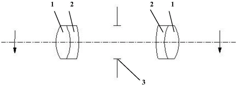
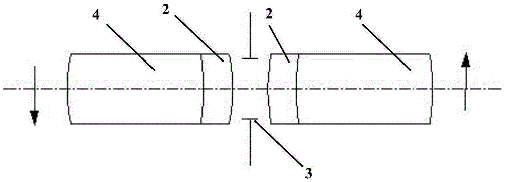
[0036]The stereoscopic endoscope has two optical observation channels, and the structural parameters of each observation channel are the same. For stereoscopic endoscopes, people do not need to observe the optical images directly, but observe the electronic images on the display. Therefore, it does not need eyepieces, which is different from rigid endoscopes. It needs to image the image of the last group of image transfer system on the pixel surface of CCD or CMOS device. This system uses two CCD or CMOS devices at the same time, and the space layout must be considered in the design.

[0037] The stereoscopic endoscope optical system of the present invention will be described in detail below with reference to the accompanying drawings and the optical design data table 1.

[0038] The objective lens adopts a reverse telephoto structure with two plano-concave lenses in front of the aperture stop. The two plano-concave lenses can well balance the on-axis and off-axis aberrations ...


PUM


Abstract

The invention discloses a stereoscopic endoscope electronic imaging optical system. Hopkins rod lenses, more than one of image transferring doublet lenses, rhombic prisms, imaging doublet lenses, single lenses and protective windows are sequentially arranged behind an objective lens and a 1:1 image transferring system composed of three groups of rod lenses which are in structural symmetry along a light ray transmitting direction; the stereoscopic endoscope electronic imaging optical system directly magnifies an image of the image transferring system to a CCD or CMOS pixel surface, and the axial magnification ranges from 1.1 to 2; the Hopkins rod lenses are used for increasing the working length of the system, and effectively reduce the number of lenses; the rhombic prisms are used for increasing the distance between the optical axes of lens groups behind two optical channels of a stereoscopic endoscope, and satisfy spatial layout requirements of two CCD or CMOS devices; and the imaging doublet lenses and the single lenses are used for magnifying images, and participate in system distortion correction so as to reduce the distortion of the system.

Description

technical field [0001] The invention belongs to the technical field of optical design, and in particular relates to the design of an electronic imaging optical system of a three-dimensional endoscope with small distortion and large field of view. Background technique [0002] Minimally invasive surgery has become the development direction of various fields of surgical medicine in the world today. Minimally invasive surgery has many advantages, such as less damage to patients, less pain for patients during surgery, and shorter recovery time after surgery, and it is more and more widely used. The development of any minimally invasive surgery is inseparable from the hard tube endoscope. Rigid tube endoscopes are welcomed by patients and surgeons due to their advanced technology, convenient application, product diversification and specialization. At present, various rigid tube endoscopes such as cystoscope, hysteroscope, laryngoscope, sinus mirror, laparoscope and arthroscope ...

Claims


Application Information

Patent Timeline
IPC IPC(8): G02B23/24
CPCG02B23/2407G02B23/2484
Inventor 王树新李建民苏赫李进华喻宏波
Owner TIANJIN UNIV
Learn More