
Rotor type double-stage oil pump

A technology of oil pump and rotor type, which is applied in the field of rotor type two-stage oil pump structure, and can solve the problem of high cost

Inactive Publication Date: 2016-01-13
HUNAN OIL PUMP
View PDF9 Cites 2 Cited by
  • Summary
  • Abstract
  • Description
  • Claims
  • Application Information

AI Technical Summary

Problems solved by technology

[0003] The purpose of the present invention is to overcome the deficiency of high cost of the existing gear type two-stage pump and provide a rotor type two-stage oil pump with compact structure and low cost

Method used


Image

  • Rotor type double-stage oil pump
  • Rotor type double-stage oil pump

Examples


Embodiment Construction

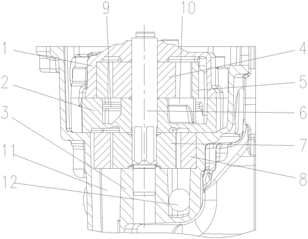
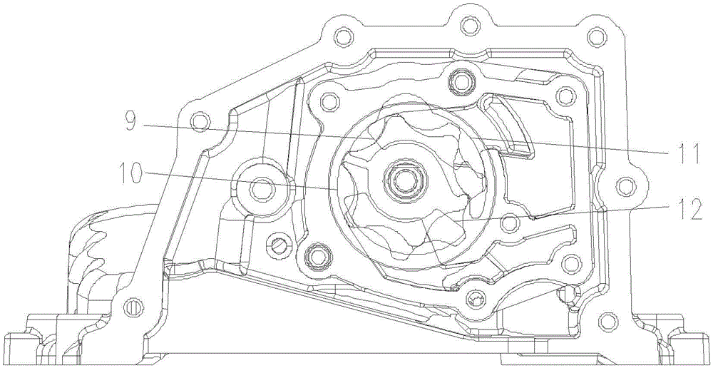
[0009] Such as figure 1 , 2 A rotor-type two-stage oil pump is shown, which includes a main pump body 1, a main pump inner rotor 4, a main pump outer rotor 5, a driving shaft 6, an intermediate partition plate 2, an auxiliary pump body 3, and an inner Rotor 7, auxiliary pump outer rotor 8; the main pump body 1 is located above the auxiliary pump body 3, the middle partition 2 is located between the main pump body 1 and the auxiliary pump body 3, the The middle partition plate 2 is provided with a main pump oil inlet 9 and a main pump oil outlet 10, and the lower part of the auxiliary pump body 3 is provided with an auxiliary pump oil inlet 11 and an auxiliary pump oil outlet 12; the main pump The inner rotor 4 and the main pump outer rotor 5 are located in the rotor cavity of the main pump body 1, and the auxiliary pump inner rotor 7 and the auxiliary pump outer rotor 8 are located in the rotor cavity of the auxiliary pump body 3; the drive shaft 6 is simultaneously Through ...


PUM


Abstract

The invention provides a rotor type double-stage oil pump which comprises a primary pump body, a primary pump inner rotor, a primary pump outer rotor, a drive shaft, a middle partition plate, a secondary pump body, a secondary pump inner rotor and a secondary pump outer rotor, wherein the primary pump body is positioned above the secondary pump body; the middle partition plate is positioned between the primary pump body and the secondary pump body; a primary pump oil inlet and a primary pump oil outlet are formed in the middle partition plate; the lower part of the secondary pump body is provided with a secondary pump oil inlet and a secondary pump oil outlet; the primary pump inner rotor and the primary pump outer rotor are positioned in a rotor cavity of the primary pump body; the secondary pump inner rotor and the secondary pump outer rotor are positioned in a rotor cavity of the secondary pump body; the drive shaft simultaneously penetrates through the primary pump body, the middle partition plate and the secondary pump body; the primary pump inner rotor and the secondary pump inner rotor are mounted on the drive shaft. According to the technical scheme, a rotor with relatively low cost is used to replace a gear with relatively high gear, so that the oil pump is more compact in structure and lower in cost.

Description

technical field [0001] The invention relates to an internal combustion engine oil pump, in particular to a rotor type two-stage oil pump structure. Background technique [0002] On some engineering machinery with uneven working sites or vehicle engines with a large climbing gradient, an auxiliary pump is generally added to suck the oil that cannot reach the bottom of the oil pan due to the tilt of the engine back to the bottom of the oil pan to ensure oil The oil level of the sump will prevent the oil pump from sucking air, resulting in gas in the fuel, which will adversely affect the engine. In order to solve this problem, the existing technology usually integrates the main pump and the auxiliary pump to form a two-stage pump, but the existing two-stage pumps all adopt a mature gear pump structure, which has the disadvantage of high cost and is not conducive to Promote on small vehicles. Contents of the invention [0003] The purpose of the present invention is to overc...

Claims


Application Information

Patent Timeline
Patent Type & Authority Applications(China)
IPC IPC(8): F16N13/20
Inventor 许仲秋向志奇刘光明阳波
Owner HUNAN OIL PUMP
Learn More