A low stiffness clutch and a driven mechanism used therein

A clutch and low stiffness technology, applied in the field of clutches, can solve the problems of reducing the resonance frequency of the driveline, reducing the torsional vibration of the driveline, reducing the natural frequency of the driveline, etc., to improve the layout space, reduce vibration and noise, and increase the layout radius. Effect

Active Publication Date: 2018-03-27
周坤鹏
View PDF7 Cites 0 Cited by
  • Summary
  • Abstract
  • Description
  • Claims
  • Application Information

AI Technical Summary

Problems solved by technology

Facts have proved that the traditional driven disc clutch torsional damper can reduce the torsional vibration of the drive train to a certain extent, but it cannot reduce the resonance frequency of the drive train below the engine idle speed
The reason is that the rigidity of the torsional damper of the traditional clutch is too large, which cannot reduce the natural frequency of the drive train below the idle speed; in terms of its structure, the driven part of the traditional clutch does not have enough space to arrange a damping spring with a lower stiffness
[0006] The stiffness K of the clutch generally depends on the following aspects: the arrangement arc length L of the damping spring of the clutch damper, the transmission torque Fn, the number n of damping springs, the torsion angle α and the arrangement radius R; and the arrangement arc of the damping spring The length L depends on the torsion angle α of the damping spring arrangement and the arrangement radius R, and its relationship is L=R α; the larger the arrangement radius R, the larger the torsion angle α, and the greater the arc length L of the damping spring arrangement; the clutch stiffness There is a relationship between K and arc length L, Fn=n·K·L·R=n·K·R 2 α; when the transmission torque Fn is constant and the torsion angle α of the damping spring arrangement is constant, the larger the arrangement radius R is, the smaller the stiffness K of the damping spring is, that is, the larger the layout space of the damping spring of the clutch damper , the lower the clutch stiffness; the traditional clutch damper has a very small layout radius R due to the structural characteristics of its driven part, resulting in a large stiffness K

Method used


Image

  • A low stiffness clutch and a driven mechanism used therein
  • A low stiffness clutch and a driven mechanism used therein
  • A low stiffness clutch and a driven mechanism used therein

Examples


Embodiment Construction

[0041]The following will clearly and completely describe the technical solutions in the embodiments of the present invention with reference to the accompanying drawings in the embodiments of the present invention. Obviously, the described embodiments are only some, not all, embodiments of the present invention. Based on the embodiments of the present invention, all other embodiments obtained by persons of ordinary skill in the art without making creative efforts belong to the protection scope of the present invention.

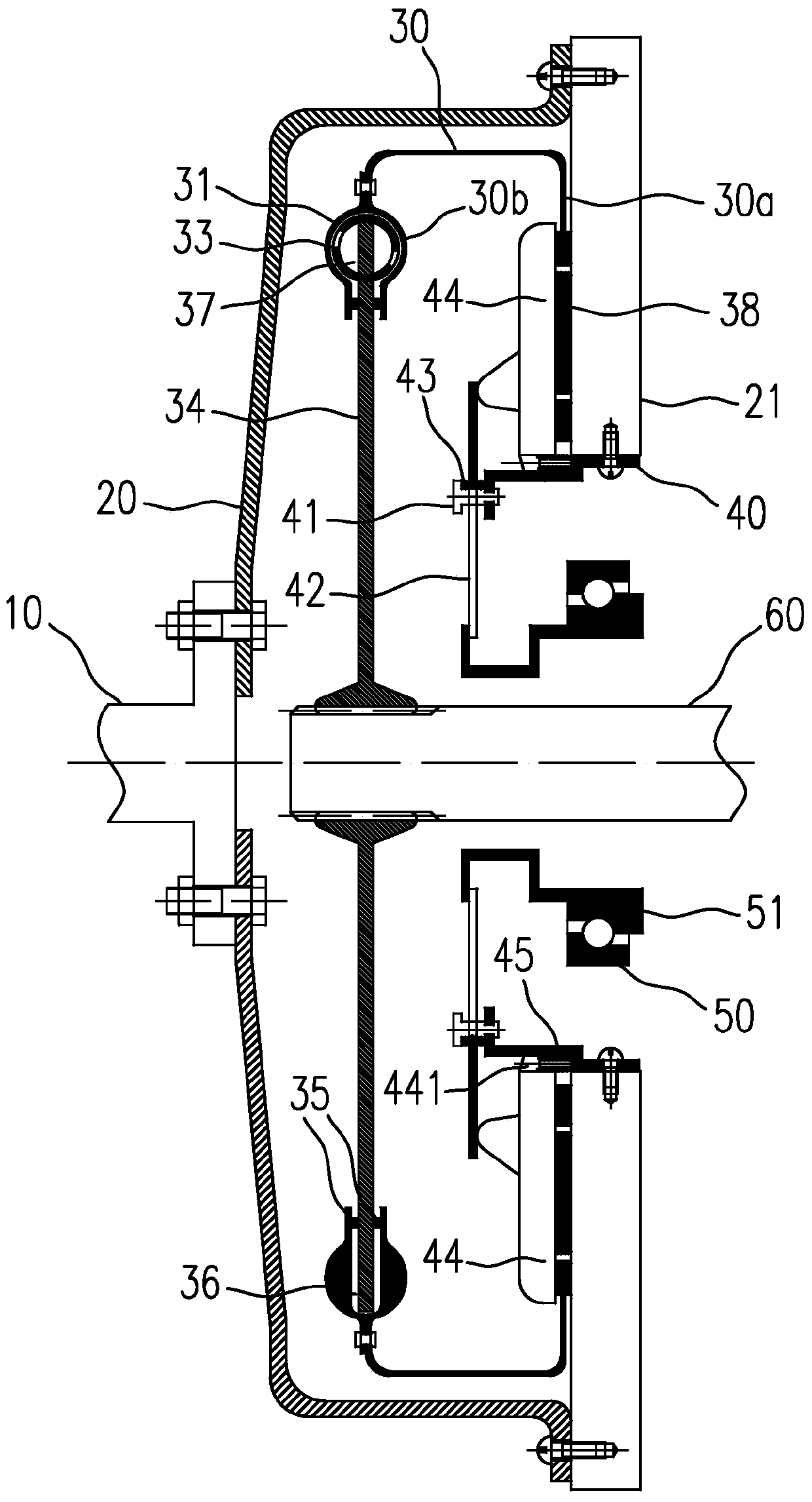
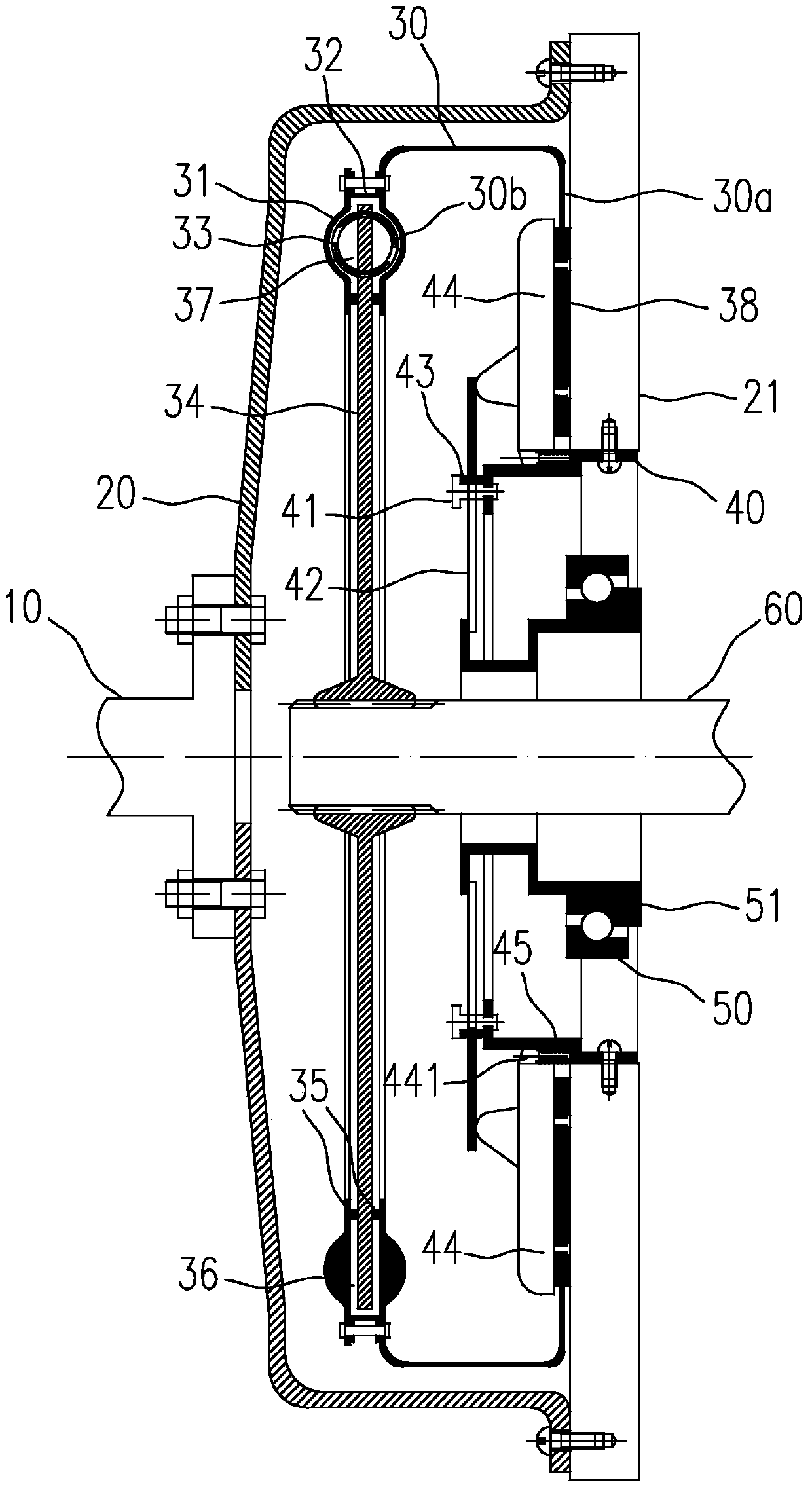
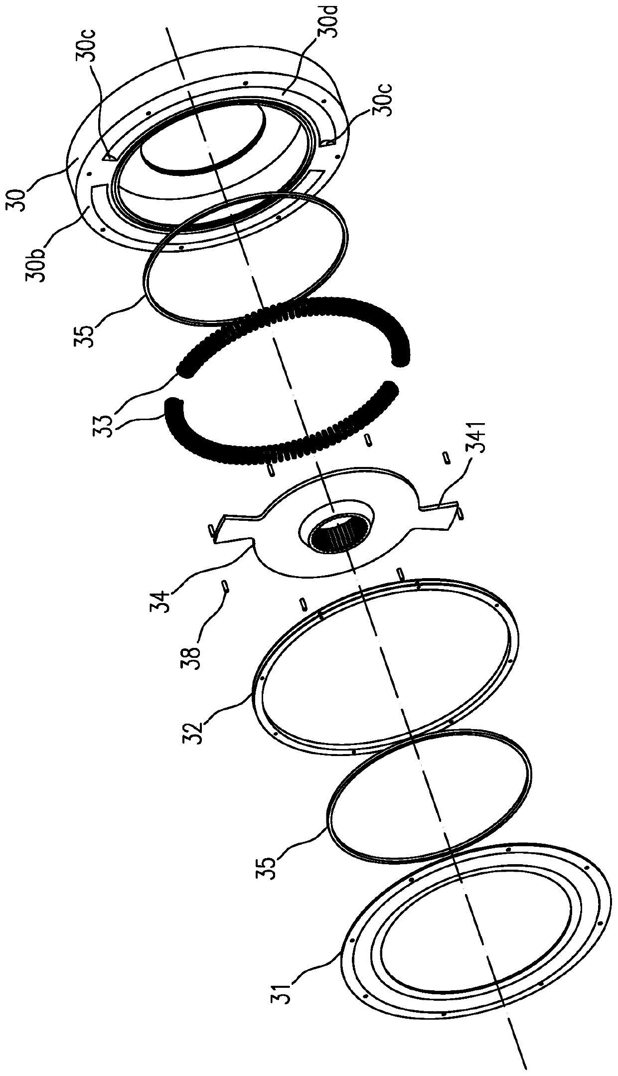
[0042] The low stiffness clutch in the present invention includes the following components: engine crankshaft 10 , driving mechanism, driven mechanism, pressing mechanism, separating mechanism and output shaft 60 . The above components are described in detail below:

[0043] 1. Active mechanism

[0044] Such as Figure 1a , Figure 1b As shown, the active mechanism is mainly composed of a clutch housing 20 and a flywheel 21; the clutch housing 20 is fixedly c...


PUM


Abstract

The invention relates to a low stiffness clutch and a driven mechanism used therein. The low-stiffness clutch includes the following components: engine crankshaft, driving mechanism, driven mechanism, pressing mechanism, separating mechanism and output shaft, wherein the driven mechanism includes an annular driven part, and one side of the driven part is provided with a The fixed edge and / or friction disc extending radially inward is provided with a flanging on the other side, and the fixed edge is in the shape of a ring with a round hole in the middle; The radial length of the disk matches the radial length of the flange; a torsional vibration damping device is interposed between the cover disk and the flange. The present invention introduces a lower rigidity into the automobile transmission system, which can better control the torsional vibration of the transmission system, reduce the vibration and noise of the transmission system, improve the comfort of the vehicle, and improve the performance of each module of the transmission system such as the transmission, differential, etc. service life of gearboxes, etc.

Description

technical field [0001] The invention belongs to a clutch in a vehicle transmission system, in particular to a low-rigidity clutch and a driven mechanism used therein. Background technique [0002] In recent years, with the continuous application of high technology in automobiles, the speed and output torque of the engine have also been greatly improved, which makes the transmission, frame and other components of the automobile produce greater noise and vibration, and even the rattle of the transmission. sound and the roar of the frame. The reason is that the transmission system of the automobile has become a multi-degree-of-freedom torsional vibration system due to its uneven mass distribution, which produces a strong resonance phenomenon under the excitation of the engine load. At this time, the load on each component also doubles. Noise and vibration are inevitable, and the fatigue life of parts is also greatly reduced. [0003] Numerous tests have shown that the torsion...

Claims


Application Information

Patent Timeline
Patent Type & Authority Patents(China)
IPC IPC(8): F16D13/58F16D13/76F16D13/71F16F15/134
Inventor 周坤鹏
Owner 周坤鹏
Why Eureka
Try Eureka