
Soil lifting system and soil lifting method for building deep foundation pit construction in narrow area

A deep foundation pit and area technology, applied in construction, infrastructure engineering, excavation, etc., can solve the problems of difficult excavation of the earthwork under the support, small clear distance between supports, and large internal support area, so as to shorten the construction period and reduce pollution. The effect of small size and simple construction equipment

Active Publication Date: 2017-03-22
CHINA CONSTR FIRST DIV GROUP CONSTR & DEV +1
View PDF6 Cites 0 Cited by
  • Summary
  • Abstract
  • Description
  • Claims
  • Application Information

AI Technical Summary

Problems solved by technology

[0003] The purpose of the present invention is to provide a soil lifting system and soil lifting method for building deep foundation pit construction in narrow areas, so as to solve the problem of small site, large internal support area, small net distance between supports and earthwork under supports in the construction of narrow areas in the prior art. Excavation is difficult, there are few excavation paths, and the technical problems that earth excavation cannot be completed by grading in the conventional way, and due to the lack of material storage yards, earth-moving vehicles need to drive to the bottom of the foundation pit to transport earth, and cannot go outside during morning and evening traffic peaks and rainy days The construction progress was hindered during transportation, and the technical problems of greatly prolonging the construction period

Method used


Image

  • Soil lifting system and soil lifting method for building deep foundation pit construction in narrow area
  • Soil lifting system and soil lifting method for building deep foundation pit construction in narrow area
  • Soil lifting system and soil lifting method for building deep foundation pit construction in narrow area

Examples


Embodiment Construction

[0050] The principles and features of the present invention are described below in conjunction with the accompanying drawings, and the examples given are only used to explain the present invention, and are not intended to limit the scope of the present invention.

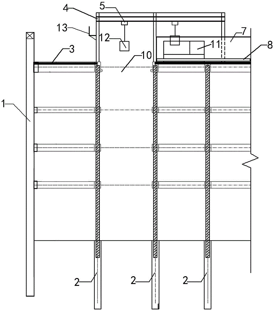
[0051] Such as figure 1, a soil lifting system for deep foundation pit construction in a narrow area, comprising a foundation pit support system, vertical earth lifting equipment and a soil pile platform, the foundation pit support system includes a foundation pit surrounding protection pile 1, a foundation pit column pile 2 and concrete support 3, characterized in that:

[0052] The concrete support 3 includes several roads from top to bottom, and the first concrete support 31 around the hole 10 is used for large-scale sealing, as the first sealing 32 for arranging earth lifting equipment and soil piling platforms; The sealing plate 32 is a reinforced concrete slab with a thickness ranging from 200 to 350 mm. The ...


PUM


Abstract

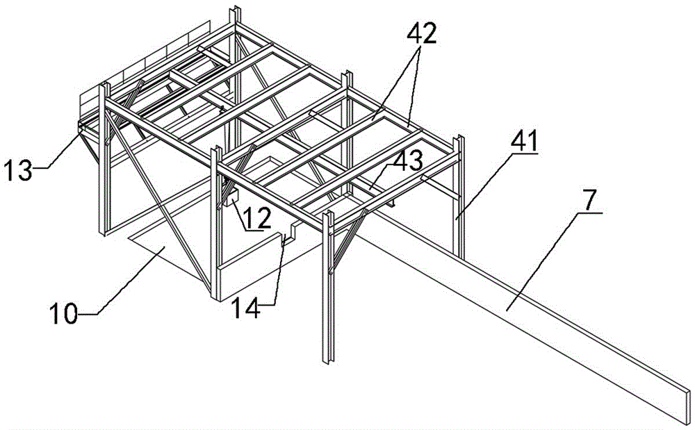
The invention discloses a soil lifting system and soil lifting method for building deep foundation pit construction in a narrow zone. A large closure plate is adopted on a first concrete support around a hole as a first closure plate for arrangement of soil lifting equipment and a soil heap platform. A steel headframe soil lifting crane is adopted in the vertical soil lifting equipment and comprises a steel headframe erected on the hole and electric blocks suspended on the steel headframe. The soil heap platform is arranged on the first closure plate around the hole and is an area defined by a retaining wall and a water retaining bank. The large closure plate is adopted on the first concrete support around the hole as the first closure plate, a conveying channel is provided for a conveying vehicle, a material storage yard is provided for subsequent construction of a main structure, and a field is provided for mounting of the soil heap platform and the steel headframe. A soil heap area is arranged on the first closure plate, and used for temporally piling up earthwork which cannot be conveyed out in time. The steel headframe soil lifting equipment is adopted, the limit of field reinforced concrete ramps is avoided, the soil outlet path is increased, the construction period is greatly shortened, and the method is especially suitable for narrow-field deep foundation pit construction.

Description

technical field [0001] The invention relates to the technical field of earthwork excavation construction, in particular to a soil lifting system and a soil lifting method for building deep foundation pit construction in a narrow area, which are applied in the construction of circular buildings with narrow construction spaces. Background technique [0002] At present, in the construction of deep foundation pits of ring buildings with narrow construction space, two problems are usually faced. On the one hand, due to the small site, large internal support area, small clear distance between supports, it is difficult to excavate the earthwork under the support, and it cannot be excavated according to the conventional method. On the other hand, due to the lack of material storage yards, earth moving vehicles have to drive to the bottom of the foundation pit to transport earth, which cannot be transported outside during morning and evening traffic peaks and rainy days, and the const...

Claims


Application Information

Patent Timeline
Patent Type & Authority Patents(China)
IPC IPC(8): B66C19/00E02D17/04
Inventor 周予启史春芳廖刚林李洪海薛刚魏健刘卫未任耀辉詹必雄付恩涛
Owner CHINA CONSTR FIRST DIV GROUP CONSTR & DEV
Learn More