Eureka AIR delivers breakthrough ideas for toughest innovation challenges, trusted by R&D personnel around the world.

A new machine room-less elevator load-bearing structure

A technology for a machine room-less elevator and a load-bearing structure, which is applied in the elevator field, can solve the problems of difficulty in adjusting levelness, low space utilization rate, insufficient top floor height, etc., and achieves the effects of levelness adjustment, high space utilization rate, and construction cost saving.

Active Publication Date: 2017-11-10
SICHER ELEVATOR
View PDF3 Cites 0 Cited by
  • Summary
  • Abstract
  • Description
  • Claims
  • Application Information

AI Technical Summary

Problems solved by technology

[0002]In the existing elevator technology, people have higher and higher requirements on the utilization rate of the well. Save a penny of construction costs, especially in the form of high housing prices where an inch of land is gold. The well pattern of small wells and small top floors can save more construction costs, which makes people's pursuit of it more and more intense. In the past, the top floor of the well Higher, which affects the construction cost and space utilization
However, for the machine-room-less elevators with small wells and small top-floor wells, the traction machine cannot be installed due to the insufficient height of the top floor; In order to adapt to the good operation of the entire elevator, in the current elevator, when the traction machine is installed, it is often fixed, and the level of the traction machine cannot be adjusted.
Therefore, the current machine-room-less elevators with small shafts and small top-floor shafts have the problem that the height of the top floor is not enough, and the traction machine cannot be installed; the usual machine-room-less elevators have low space utilization, high construction costs and problems with the installation of the traction machine. The problem that its level is difficult to adjust

Method used


Image

  • A new machine room-less elevator load-bearing structure
  • A new machine room-less elevator load-bearing structure
  • A new machine room-less elevator load-bearing structure

Examples


Embodiment Construction

[0020] The present invention will be further described below in conjunction with the accompanying drawings and embodiments, but not as a basis for limiting the present invention.

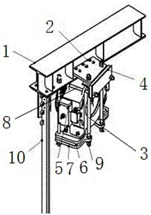
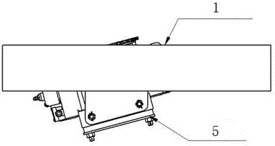
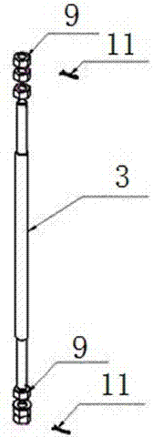
[0021] Example. The load-bearing structure of a new machine room-less elevator consists of figure 1 , figure 2 and image 3 As shown, including the load-bearing beam 1, the bottom of the load-bearing beam 1 is provided with a connecting plate 2 and a round hole, the round hole is located next to the connecting plate 2, and the connecting plate 2 is also provided with a round hole, the round hole at the bottom of the load-bearing beam 1 and the connection Threaded rods 3 are pierced in the round holes on the plate 2, and the lower part of the threaded rods 3 is pierced with a fixing plate 7, and the upper and lower ends of the threaded rods 3 are provided with nuts, and the fixing plate 7 is provided with a traction machine 5. The traction machine 5 is located below the connecting plate 2 .

[0...


PUM


Abstract

The invention discloses a novel load-bearing structure of an elevator without a machine room, which comprises a load-bearing beam (1). The bottom of the load-bearing beam (1) is provided with a connecting plate (2) and a round hole, and the round hole is located next to the connecting plate (2). The connecting plate (2) is also provided with a circular hole, and the circular hole at the bottom of the load-bearing beam (1) and the circular hole on the connecting plate (2) are threaded with a threaded rod (3), and the bottom of the threaded rod (3) is threaded through A fixed plate (7) is provided, nuts are provided at the upper and lower ends of the threaded rod (3), the fixed plate (7) is provided with a traction machine (5), and the traction machine (5) is located at the below. The invention has the characteristics that the traction machine can be well installed, the space utilization rate is high, the construction cost is low and the levelness of the traction machine can be adjusted.

Description

technical field [0001] The invention relates to the technical field of elevators, in particular to a novel machine room-less elevator load-bearing structure. Background technique [0002] In the existing elevator technology, people have higher and higher requirements on the utilization rate of the shaft. In high-rise buildings, less space in the elevator shaft means that the construction cost can be saved, especially in high housing prices where every inch of land is gold. In terms of form, the well mode of small well and small top floor can save more construction costs, which makes people's pursuit of it more and more intense. In the past, the top floor of the well was higher, which affected the construction cost and space utilization. However, for the machine-room-less elevators with small wells and small top-floor wells, the traction machine cannot be installed due to the insufficient height of the top floor; In order to adapt to the good operation of the entire elevator...

Claims


Application Information

Patent Timeline
Patent Type & Authority Patents(China)
IPC IPC(8): B66B11/04B66B11/00
Inventor 费权钱沈明明张晓强李仁顾佳金胡勤惠沈培华
Owner SICHER ELEVATOR
Why Eureka
Eureka Blog
Learn More