Rotary tillage and ditching device

A technology of mounting seat and frame, which is applied to shovels, plows, agricultural machinery and implements, etc., can solve the problems of unsuitable for high-humidity field ditching, untidy ditching and complex structure of rotary tillage cutterhead, etc., to achieve Good ditching effect, simple and reasonable structure, and low ditching resistance

Inactive Publication Date: 2016-01-13
HUNAN AGRICULTURAL UNIV
View PDF7 Cites 6 Cited by
  • Summary
  • Abstract
  • Description
  • Claims
  • Application Information

AI Technical Summary

Problems solved by technology

There are two main methods of mechanical ditch opening. One is to open the ditch first and then sow. This method uses different machines to complete the ditch opening and sowing operations successively, which is time-consuming and labor-intensive, and causes repeated pressure on the ground by the machine. solid, and the original ditch may be destroyed during sowing; the other is to use a combined operation seeder to complete the opening of the ditch at the same time as the sowing operation
At present, there are two main ways to open the ditch with the national ditching machine. One is to break the soil with a rotary tiller, and then use the rotary tiller to clear the complete ditch with the soil clearing shovel. This method is used to open the ditch. The ditch type is relatively neat, but the structure of the rotary tillage cutter head is complicated, it is inconvenient to install and disassemble, and it is not suitable for ditching in high-humidity fields
The other is to rely on the traction force of the tractor and use two-sided plows to open the ditch. The structure of the whole machine using this method is simple and light in weight, but the ditch shape is not neat enough, and the ditching resistance is relatively large, and the power consumption is high.

Method used


Image

  • Rotary tillage and ditching device
  • Rotary tillage and ditching device
  • Rotary tillage and ditching device

Examples


Embodiment Construction

[0020] The present invention will be described in further detail below in conjunction with the accompanying drawings and specific embodiments.

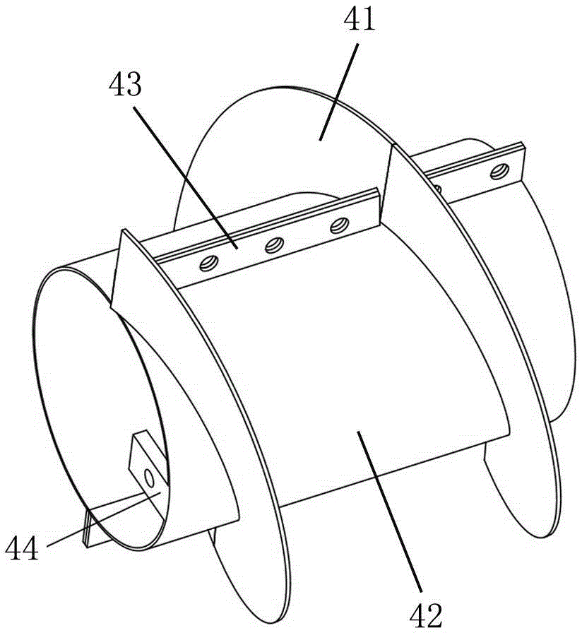
[0021] Such as figure 1 and figure 2 As shown, the rotary tillage ditching device of the present invention includes a frame 1 and a rotary tillage mechanism 2 installed on the frame 1, wherein the rotary tillage mechanism 2 can adopt the prior art, and the frame 1 is mounted on the rotary tillage mechanism 2 The front of the forward direction is provided with a front plow 3 for opening the ditch, and two auger shaping mechanisms 4 are installed on the rotary tillage shaft 21 of the rotary tillage mechanism 2, and the two auger shaping mechanisms 4 are located at the rear of the front plow 3 , each auger shaping mechanism 4 has an auger blade 41 spirally wound around the rotary tillage shaft 21, the helical directions of the auger blades 41 of the two auger shaping mechanisms 4 are opposite, and with the rotary movement of the rotary...


PUM


Abstract

The invention discloses a rotary tillage and ditching device. The rotary tillage and ditching device comprises a frame and a rotary tillage mechanism arranged on the frame. A forward plough used for opening up a trench is arranged ahead of a heading direction of the rotary tillage mechanism on the frame. A rotary tillage shaft of the rotary tillage mechanism is provided with two packing auger shaping mechanisms located behind the forward plough. All the packing auger shaping mechanisms are provided with auger blades spirally rotating around the rotary tillage shaft. The packing auger blades of the two packing auger shaping mechanisms are opposite in spiral directions and push top soil subjected to soil-turning operation by the forward plough to two sides of the opened trench when performing rotary motion along with the rotary tillage shaft. The rotary tillage and ditching device is advantaged by being simple and reasonable in structure, low in manufacture cost, small in resistance of trench digging, fine in trench digging quality and low in power consumption.

Description

technical field [0001] The invention relates to the technical field of agricultural machinery, in particular to a rotary tillage ditching device. Background technique [0002] There is a lot of rain in the southern part of our country. When planting, it is generally necessary to open a box ditch every few rows for drainage or for irrigation in case of drought. There are two main methods of mechanical ditch opening. One is to open the ditch first and then sow. This method uses different machines to complete the ditch opening and sowing operations successively, which is time-consuming and labor-intensive, and causes repeated pressure on the ground by the machine. It is solid, and the original ditch pattern may be destroyed during sowing; the other is to use a combined operation seeder to complete the opening of the ditch while sowing. At present, there are two main ways to open the ditch with the national ditching machine. One is to break the soil with a rotary tiller, and th...

Claims


Application Information

Patent Timeline
Patent Type & Authority Applications(China)
IPC IPC(8): A01B49/02
Inventor 罗海峰吴明亮包攀峰易鹏谢伟
Owner HUNAN AGRICULTURAL UNIV
Why Eureka
Try Eureka