
Locomotive hardware-in-the-loop simulation device, system and method

A semi-physical simulation and real-time simulation technology, applied in general control systems, control/regulation systems, instruments, etc. Physical controller software and hardware function verification and other issues

Active Publication Date: 2018-11-30
CSR ZHUZHOU ELECTRIC LOCOMOTIVE RES INST
View PDF8 Cites 0 Cited by
  • Summary
  • Abstract
  • Description
  • Claims
  • Application Information

AI Technical Summary

Problems solved by technology

[0024] In view of this, the object of the present invention is to provide a locomotive semi-physical simulation device, system and method, which can effectively solve the problem of the low integrity and accuracy of the existing simulation system and method semi-physical simulation, which cannot accurately control the real object. Verify the software and hardware functions of the device, and at the same time improve the technical problems with low cycle time, efficiency and enforceability

Method used


Image

  • Locomotive hardware-in-the-loop simulation device, system and method
  • Locomotive hardware-in-the-loop simulation device, system and method
  • Locomotive hardware-in-the-loop simulation device, system and method

Examples


Embodiment 1

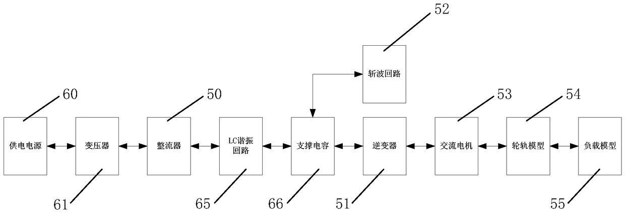
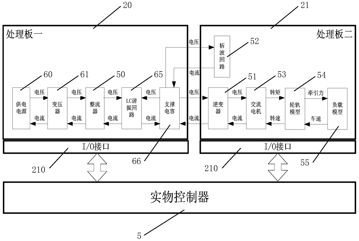
[0144] As attached Figure 4 As shown, the functional unit 6 includes a processing board 20 (CPU1 board) and a high-speed processing board 24 (FPGA1 board);

[0145] The processing board 20 includes: a power supply simulation unit 60 and a transformer simulation unit 61;

[0146] The high-speed processing board 24 includes: a rectifier one simulation unit 62, a rectifier two simulation unit 63, a rectifier three simulation unit 64, an LC resonance circuit simulation unit 65, and a supporting capacitor simulation unit 66;

[0147] Function unit two 7 includes: processing board two 21 (CPU2 board) and high-speed processing board two 25 (FPGA2 board);

[0148] The second processing board 21 includes: wheel-rail model one 75 and wheel-rail model two 77;

[0149] High-speed processing board two 25 includes: inverter one simulation unit 70, chopper circuit one simulation unit 71, inverter two simulation unit 72, chopper circuit two simulation unit 73, AC motor one simulation unit 74 and AC mo...

Embodiment 2

[0157] As attached Figure 5 As shown, the functional unit 6 includes a processing board 20 (CPU1 board) and a high-speed processing board 24 (FPGA1 board);

[0158] The processing board 20 includes: a power supply simulation unit 60, a transformer simulation unit 61, an LC resonance circuit simulation unit 65, and a support capacitor simulation unit 66;

[0159] The high-speed processing board 24 includes: a rectifier simulation unit 62, a rectifier simulation unit 63, and a rectifier simulation unit 64;

[0160] Function unit two 7 includes: processing board two 21 (CPU2 board) and high-speed processing board two 25 (FPGA2 board);

[0161] The second processing board 21 includes: wheel-rail model one 75 and wheel-rail model two 77;

[0162] High-speed processing board two 25 includes: inverter one simulation unit 70, chopper circuit one simulation unit 71, inverter two simulation unit 72, chopper circuit two simulation unit 73, AC motor one simulation unit 74 and AC motor two simulati...

Embodiment 3

[0170] As attached Image 6 As shown, the functional unit 6 includes a processing board 20 (CPU1 board) and a high-speed processing board 24 (FPGA1 board);

[0171] The processing board 20 includes: a power supply simulation unit 60, a transformer simulation unit 61, an LC resonance circuit simulation unit 65, and a support capacitor simulation unit 66;

[0172] The high-speed processing board 24 includes: a rectifier simulation unit 62, a rectifier simulation unit 63, and a rectifier simulation unit 64;

[0173] Function unit two 7 includes: processing board two 21 (CPU2 board) and high-speed processing board two 25 (FPGA2 board);

[0174] The second processing board 21 includes: wheel-rail model one 75 and wheel-rail model two 77;

[0175] High-speed processing board two 25 includes: inverter one simulation unit 70, chopper circuit one simulation unit 71, inverter two simulation unit 72, chopper circuit two simulation unit 73, AC motor one simulation unit 74 and AC motor two simulatio...


PUM


Abstract

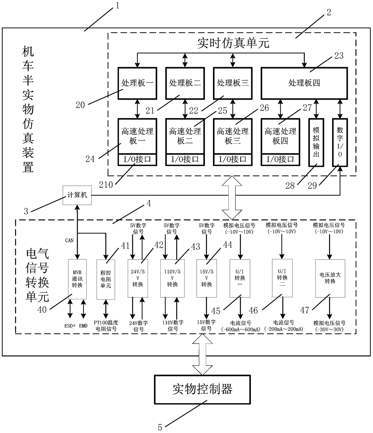
The invention discloses a locomotive semi-physical simulation device, system and method. The device comprises a real-time simulation unit, a computer and an electrical signal conversion unit. The computer converts a control instruction for simulating an upper-layer network control system into a bus communication protocol, and then sends the bus communication protocol to a communication conversion unit of the electrical signal conversion unit. The communication conversion unit sends the control instruction to an external physical controller, the physical controller outputs a control signal to a controlled object model according to the control instruction, the control signal is sent to a real-time simulation unit via the electrical signal conversion unit, the real-time simulation unit calculates a output result of a state signal of the controlled object model according to the control signal, the output result is sent to the physical controller via the electrical signal conversion unit, and the physical controller sends the state signal of the controlled object model back to the computer via the communication conversion unit. The technical problems that simulation integrity and precision of an existing system are not high, function verification cannot be accurately performed, the modification period is long, and efficiency and performability are low are solved.

Description

Technical field [0001] The present invention relates to electrical system simulation technology, in particular to a semi-physical simulation device, system and method applied to locomotives, especially locomotive traction systems. The present invention can also be applied to the semi-physical simulation of other similar electrical systems. Background technique [0002] As an important branch of electronic technology, power electronic technology can realize the conversion and control of electric energy. It has been widely used in various fields of the national economy such as industry, transportation, and national defense. With the deepening of national energy conservation and emission reduction policies, the application of power electronic technology in all walks of life in our country will become more popular and widespread. Since the power electronic system is a complex non-linear system, the design and analysis are more difficult, so it usually requires a long design and devel...

Claims


Application Information

Patent Timeline
Patent Type & Authority Patents(China)
IPC IPC(8): G05B17/02G05B23/02
Inventor 徐立恩
Owner CSR ZHUZHOU ELECTRIC LOCOMOTIVE RES INST
Learn More