
Reverse rotation speed sensor

A sensor and thread technology, applied in the field of anti-rotation speed sensors, can solve the problems of no signal reception, installation difficulty, loss, etc., and achieve the effects of strong signal reception, convenient fixing and simple structure

Inactive Publication Date: 2016-01-06
周晓
View PDF0 Cites 0 Cited by
  • Summary
  • Abstract
  • Description
  • Claims
  • Application Information

AI Technical Summary

Problems solved by technology

However, it is more difficult during the installation process, and it often causes unnecessary trouble and loss to the company due to improper installation and failure to receive signals during actual operation.

Method used


Image

  • Reverse rotation speed sensor
  • Reverse rotation speed sensor

Examples


Embodiment Construction

[0011] All features disclosed in this specification, or steps in all methods or processes disclosed, may be combined in any manner, except for mutually exclusive features and / or steps.

[0012] Any feature disclosed in this specification (including any appended claims, abstract and drawings), unless expressly stated otherwise, may be replaced by alternative features which are equivalent or serve a similar purpose. That is, unless expressly stated otherwise, each feature is one example only of a series of equivalent or similar features.

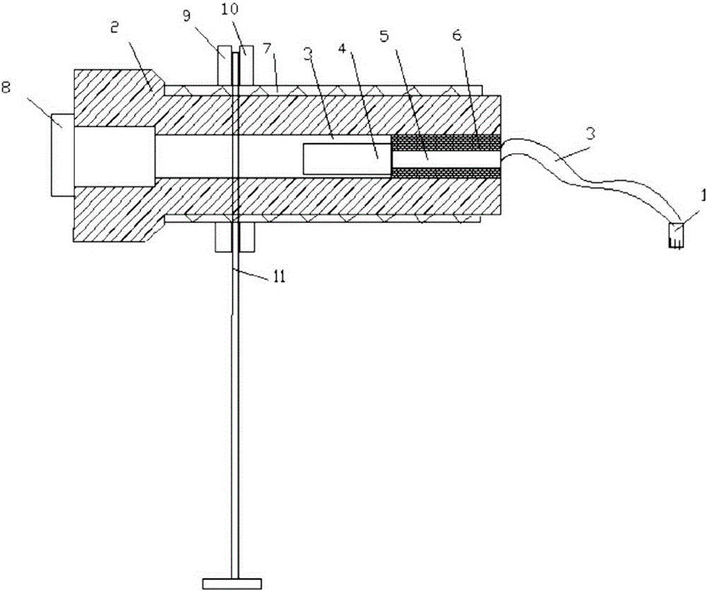
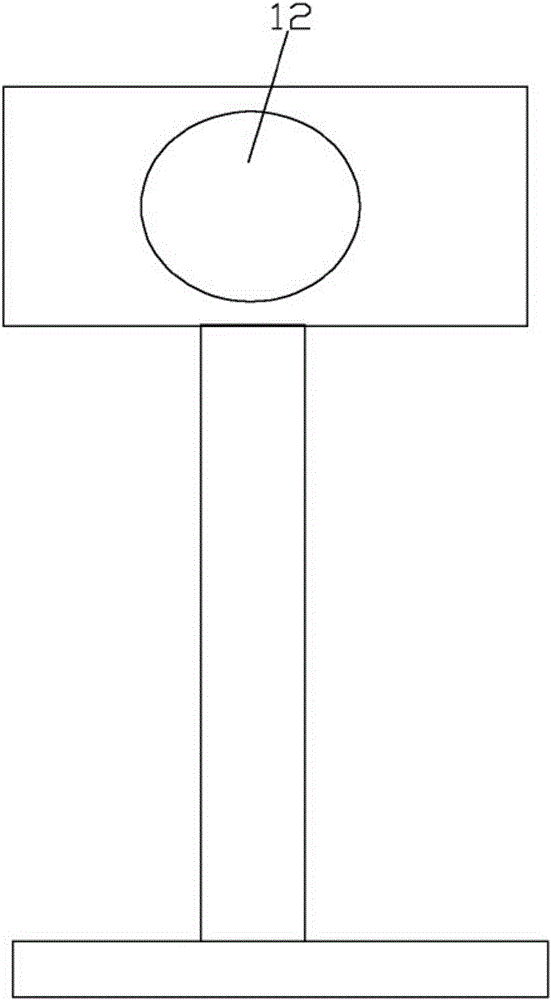
[0013] Depend on figure 1 figure 2 Described a kind of anti-speed sensor comprises receiving head 8, wire 3, magnetic steel 4, magnet guide post 5, planar coil 6, plug 1 and shell 2, has a circle thread 7 grooves on shell 2, on thread 7 Two fixed nuts are screwed, a fixed armature 11 is clamped in the middle of the nut, and a fixed hole 12 is opened on the fixed armature 11, and the diameter is the same as the outer diameter of the sensor. ...


PUM


Abstract

The invention discloses a reverse rotation speed sensor, which comprises a receiving head, a lead, a magnetic steel part, a magnetic guide column, a planar coil, a plug and a housing. The housing is provided with a circle of threads and nuts are screwed onto the threads. A fixed armature is sandwiched between the nuts. The fixed armature is provided with a fixing hole. The diameter of the fixed armature is the same with the external diameter of the sensor. The sensor is simple in structure, convenient to fix, and strong in signal reception effect.

Description

technical field [0001] The invention relates to sensors, in particular to an inverse rotational speed sensor. Background technique [0002] We know that the existing speed sensor consists of wires, magnetic steel, magnet guide posts, planar coils and plugs, and a housing. This kind of sensor is simple in structure, cheap in price, and very practical. However, it is more difficult during the installation process, and it often causes unnecessary trouble and loss to the company because the signal cannot be received during the actual operation process due to improper installation. Contents of the invention [0003] In order to overcome the problems of the prior art that it is difficult to fix and receive signals, the present invention provides an inverse rotational speed sensor which has a simple structure, is convenient to fix, and has a strong receiving signal. [0004] In order to achieve the above object, the technical solution of the present invention is: a reverse spee...

Claims


Application Information

Patent Timeline
Patent Type & Authority Applications(China)
IPC IPC(8): G01P3/487
Inventor 周晓
Owner 周晓
Learn More