Emergency release device for low-temperature fluid loading and unloading arm

A cryogenic fluid and detachment device technology, applied in the direction of gas/liquid distribution and storage, container discharge method, container filling method, etc., can solve the problem that the sealing between the valve core and the valve body is difficult to ensure, the requirement of rapid separation cannot be met, and the quality cannot be guaranteed and other issues to achieve the effect of ensuring sealing performance, light weight and compact structure

Active Publication Date: 2016-01-06
WUHAN YUANFANG SCI & TECH CO LTD OF CHINA SANJIANG SPACE GRP
View PDF9 Cites 4 Cited by
  • Summary
  • Abstract
  • Description
  • Claims
  • Application Information

AI Technical Summary

Problems solved by technology

However, the general threaded connection cannot meet the requirements of quick separation. In this case, it is necessary to install an emergency release device on the cryogenic loading and unloading arm.
[0003] At present, there are mainly two structural forms of emergency release devices on the market. One is a double ball valve structure. Although this scheme has high structural reliability and small liquid resistance of the ball valve, the sealing performance is dete...

Method used


Image

  • Emergency release device for low-temperature fluid loading and unloading arm
  • Emergency release device for low-temperature fluid loading and unloading arm
  • Emergency release device for low-temperature fluid loading and unloading arm

Examples


Embodiment Construction

[0025] The present invention will be further described in detail below in conjunction with the accompanying drawings and specific embodiments.

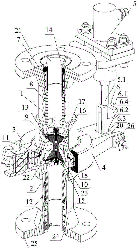
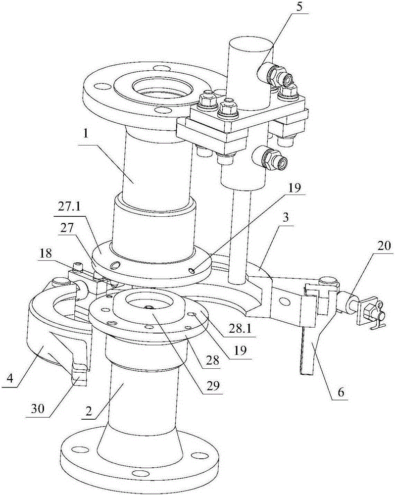
[0026] combine figure 1 , figure 2 The emergency release device for the cryogenic fluid loading and unloading arm shown includes the upper valve body 1 of the self-sealing valve, the upper valve core arranged in the upper valve body 1 of the self-sealing valve, the lower valve body 2 of the self-sealing valve, and the lower valve body 2 of the self-sealing valve. The lower valve core, the clamp assembly clamping the upper valve body 1 of the self-sealing valve and the lower valve body 2 of the self-sealing valve together, and the hydraulic cylinder 5 for driving the clamp assembly to separate.

[0027] The clip assembly includes a first clip 3, a second clip 4 rotatably connected to the first clip 3, a swing bar 20 and a push block 6, one end of the first clip 3 is connected to one end of the swing bar 20 through a rotating shaft, ...


PUM


Abstract

The invention discloses an emergency release device for a low-temperature fluid loading and unloading arm. An upper valve element of an upper valve body of a self-sealing valve and a lower valve element of a lower valve body of the self-sealing valve are oppositely arranged in an abutting manner. When a clamping hoop assembly is separated, clamping force applied to the upper valve body of the self-sealing valve and the lower valve body of the self-sealing valve disappears, the emergency release device starts to be released under the gravity effect of the self-sealing valve lower valve body, in the release process, valve ports are gradually sealed through the valve elements under the work effect of reset springs and a fluid medium, the sealing performance after separation can be effectively guaranteed, and the emergency release device is compact in structure and low in weight. The structure that the upper valve body of the self-sealing valve and the lower valve body of the self-sealing valve are fixed through the clamping hoop assembly is adopted so that the small drive force and the short drive stroke can be guaranteed. Three slopes are integrated on a push block so that the corrective logic and the reliable action of separation can be guaranteed. The measures that the overall weight of the emergency release device is reduced, and process threaded holes are formed in the valve bodies are taken, so that the self-recovery workload of the emergency release device after separation is reduced.

Description

technical field [0001] The invention relates to components of marine low-temperature fluid delivery equipment, in particular to an emergency release device for a low-temperature fluid loading and unloading arm. Background technique [0002] Cryogenic fluid loading and unloading arms can be used for land transportation (including train transportation and automobile transportation) and water transportation (including ocean transportation and river transportation). Cryogenic loading and unloading arms for ocean and river transportation are also called marine low-temperature loading and unloading arms. During the operation of the cryogenic fluid loading and unloading arm, once an emergency occurs (such as cryogenic liquid leakage, fire, or the angle of deformation of the loading and unloading arm is too large, etc.), in order to ensure that the output end (filling station, etc.) and the injection end (ships, cars, etc.) For safety, the separation needs to be completed in the sho...

Claims


Application Information

Patent Timeline
IPC IPC(8): F17C13/00F17C13/08
Inventor 余峰肖天成李庆军赵坤
Owner WUHAN YUANFANG SCI & TECH CO LTD OF CHINA SANJIANG SPACE GRP
Why Eureka
Try Eureka