
Self-cleaning waste conveying system for energy recovery

A technology for waste transportation and energy recovery, which is applied in the direction of conveyors, garbage cans, garbage collection, etc. It can solve the problems of high-rise buildings that cannot be applied, domestic waste is easy to pollute, technical requirements, and high installation requirements, so as to reduce management costs and save power. Consumption, the effect of reducing manpower consumption

Active Publication Date: 2016-01-06
ZHEJIANG UNIV
View PDF9 Cites 6 Cited by
  • Summary
  • Abstract
  • Description
  • Claims
  • Application Information

AI Technical Summary

Problems solved by technology

Although the real-time garbage transportation system solves the defect of garbage free fall, but using the garbage pallet as the carrier, some domestic garbage is easy to pollute the inner wall of the garbage transportation pipeline, which will inevitably cause peculiar smell, and the conveyor belt consumes a lot during operation.
In addition, although these advanced garbage pipes have better garbage disposal effects, they need to be installed inside the building at the beginning of the building design, which is not applicable to many existing high-rise buildings, and the technical requirements and installation requirements are high. There is a large energy consumption, which is not widely applicable at this stage

Method used


Image

  • Self-cleaning waste conveying system for energy recovery
  • Self-cleaning waste conveying system for energy recovery
  • Self-cleaning waste conveying system for energy recovery

Examples


Embodiment Construction

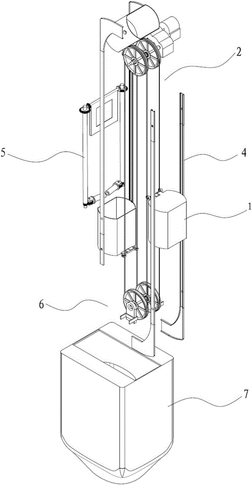
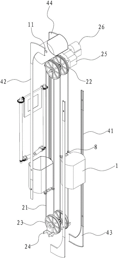
[0034] Such as figure 1 As shown, an energy recovery and self-cleaning garbage conveying system includes a lifting mechanism 2 for driving a garbage can 1, a limit rail 4, an instant stop mechanism 5 and a garbage storage box 7.

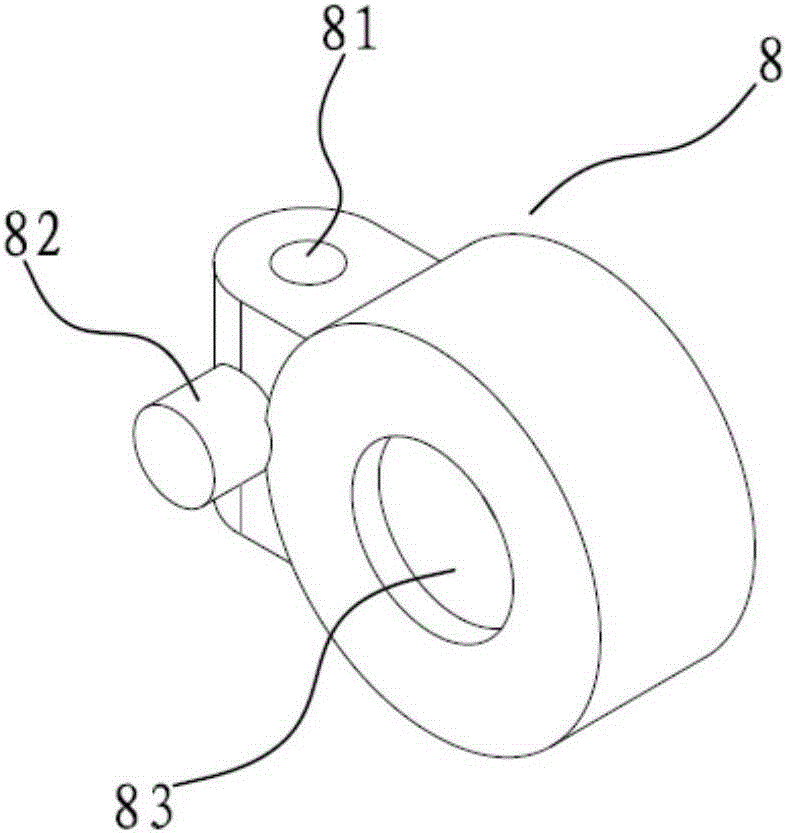
[0035] The lifting mechanism 2 is used to transport the garbage bin 1 in a cycle, including two fixed pulleys 22 and two fixed pulleys 23, which are coaxially arranged on the top and bottom of the building respectively, and the two fixed pulleys on the same vertical line form a group. Wire rope 21 is wound on the set pulley, and garbage bin 1 is fixed on the wire rope 21 by connecting seat 8 at intervals, and the distance between garbage bin 1 is fixed as the floor height, and wire rope 21 straddles two fixed pulleys up and down to form a ring.

[0036] In this embodiment, each floor corresponds to two garbage cans 1, which are respectively arranged on both sides of the device. The garbage can 1 on one side is close to the garbage disposal port of th...


PUM


Abstract

The invention discloses a self-cleaning waste conveying system for energy recovery. The self-cleaning waste conveying system for energy recovery comprises a lifting mechanism, limiting rails, instant stopping mechanisms and a waste storage bin. The lifting mechanism is used for conveying dustbins up and down in a circulating mode and comprises an annular conveying piece. A plurality of connecting bases are arranged on the annular conveying piece at intervals. The dustbins are connected to the connecting bases in a rotary mode respectively. The limiting rails are installed at the two sides of the lifting conveying mechanism and used for keeping the rising and falling movement postures of the dustbins. A waste dumping position having a non-limiting rail function is arranged close to the bottom of the lifting mechanism. The instant stopping mechanisms are arranged on all storeys and used for controlling the dustbins to stop instantly at waste throwing-in openings. The waste storage bin is arranged below the lifting mechanism and used for storing waste dumped from the dustbins in an mode. The self-cleaning waste conveying system is suitable for lifting and conveying waste of all storeys of a high-rise building; power consumption for conveying waste through an elevator is reduced, energy is saved, and emission is reduced; manpower consumption of waste disposal is reduced, and management cost is reduced.

Description

technical field [0001] The invention relates to a garbage conveying system for high-rise buildings, in particular to an energy recovery and self-cleaning garbage conveying system. Background technique [0002] High-rise waste pipes are not a new idea for waste transportation. This type of design has been widely used in high-rise buildings as early as the last century. For example, the utility model patent with the publication number CN201517279U provides a garbage recovery system for high-rise buildings, which is composed of a garbage pipeline, a garbage drop, a porous baffle, and a garbage bin. The top of the garbage pipeline is open and extends from the roof to the building. In the garbage bin at the bottom, a garbage drop is opened on each floor near the side of the pipeline and a baffle is set, and a porous baffle is arranged obliquely at the intersection of the pipeline and the garbage can. However, because the specific implementation method is that the garbage falls f...

Claims


Application Information

Patent Timeline
Patent Type & Authority Applications(China)
IPC IPC(8): B65G17/12B65G47/38B65G43/08B65F1/14
CPCY02W30/10
Inventor 徐象国孙强张一帆赵晨曦鲍静涵朱兆杰
Owner ZHEJIANG UNIV
Learn More