
Mechanical arm system and its parallelism correction method

A technique for manipulators and calibration methods, which is applied to manipulators, program-controlled manipulators, instruments, etc., and can solve problems such as the inability to ensure the parallelism between the manipulator and the machine, the difficulty of parallelism correction, and the difficulty in parallelism correction.

Active Publication Date: 2019-05-24
HIWIN TECH
View PDF13 Cites 0 Cited by
  • Summary
  • Abstract
  • Description
  • Claims
  • Application Information

AI Technical Summary

Problems solved by technology

However, the method provided by the aforementioned patents cannot arbitrarily change the angle of the robot arm according to different work requirements, and if the machining accuracy of the bearing surface is not good, the parallelism between the robot arm and the machine cannot be ensured
[0004] In fact, the robot arm is often used in a variety of tasks, and its coordinate system is difficult to match the coordinate system of the corresponding working device (such as pick-and-place platform, orifice plate, etc.), so the end surface of the robot arm corresponds to The parallelism between the working planes of the working device is quite difficult to correct. In particular, the robot arm may require a tilted working plane with a relatively complex coordinate system. In this case, it is even more difficult to perform parallelism correction.

Method used

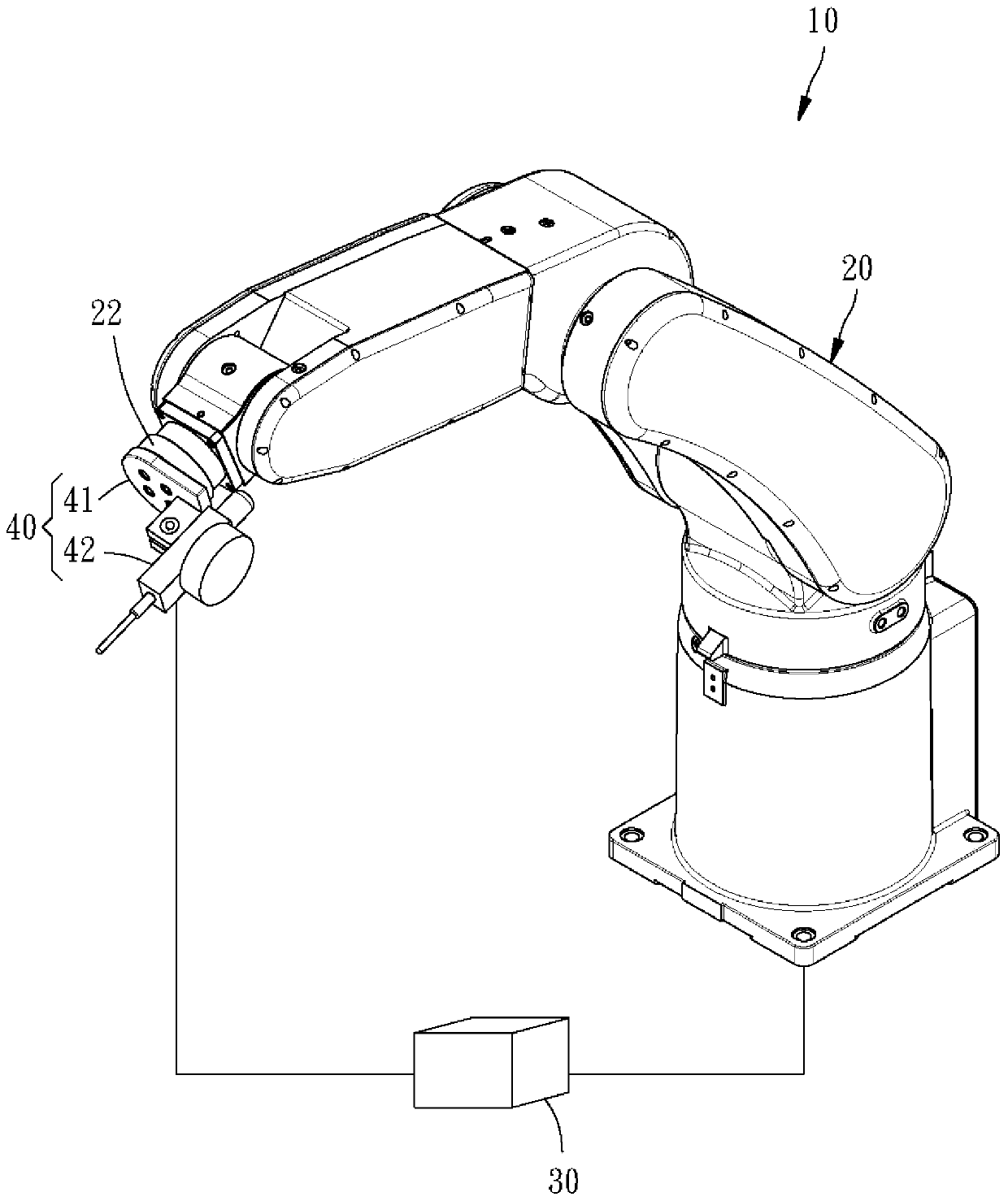
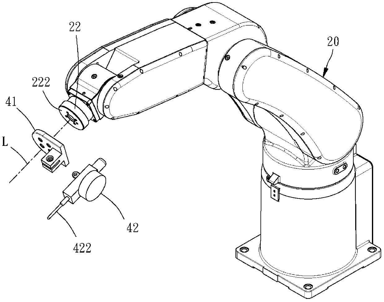
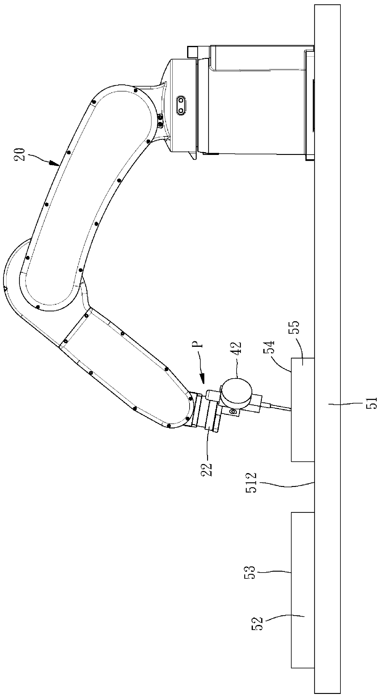

Image

  • Mechanical arm system and its parallelism correction method
  • Mechanical arm system and its parallelism correction method
  • Mechanical arm system and its parallelism correction method

Examples


Embodiment Construction

[0020] The detailed structure, features, assembly or usage of the robotic arm system and its parallelism correction method provided by the present invention will be described in the subsequent detailed description of the implementation. However, those skilled in the field of the present invention should understand that these detailed descriptions and specific examples for implementing the present invention are only for illustrating the present invention, and are not intended to limit the scope of patent application of the present invention.

[0021] The applicant first explains here that in the embodiments and drawings to be described below, the same reference numerals denote the same or similar components or structural features. Secondly, when it is mentioned that a component is set on another component, it means that the aforementioned component is directly set on the other component, or that the aforementioned component is indirectly set on the other component, that is, ther...


PUM


Abstract

The present invention relates to a robot arm system and a method for calibrating a parallelization degree thereof. The robot arm system includes an robot arm, a controller, and a parallelization degree calibrating device. The robot arm includes an end shaft, and the end shaft has an end cross section. The parallelization degree calibrating device has at least a range finder and is installed at the end cross section. The method for calibrating a parallelization degree of a robot arm system includes: a step of moving the end shaft to a calibrating position adjacent to a datum plane; a step of transmitting a measurement signal to the controller by measuring a distance difference between at least three measured points on the datum plane and the end by using the parallelization calibrating device; and a step of controlling a posture of the robot arm according to the measurement signal and enabling the distance between the measured points and the end cross section to be same as each other by using the controller. Thereby, the robot arm system and the method for calibrating a parallelization degree thereof enables the robot arm to rapidly perform accurate parallelization and form a working plane in various working situations.

Description

technical field [0001] The present invention is related to a mechanical arm, in particular to a mechanical arm system with parallelism correction function and its parallelism correction method. Background technique [0002] When the mechanical arm performs specific work, an end face thereof often needs to be parallel to a working plane, so that an end effector disposed on the end face can work smoothly. For example, the end effector may be a gripper for gripping a shaft and inserting the shaft into an insertion hole on the working plane of an orifice plate, the robotic arm must cause the shaft to The insertion hole is perpendicular to the working plane, at this time, the end surface must be parallel to the working plane. [0003] Please refer to the U.S. patent US5218550, which provides a bearing surface on a machine platform, and fixes the base of a robot arm on the bearing surface so that a specific part of the robot arm is parallel to a specific axis of the machine platf...

Claims


Application Information

Patent Timeline
Patent Type & Authority Patents(China)
IPC IPC(8): B25J9/18G01B21/24
CPCB25J11/00
Inventor 谢武灯陈汉雄郭长信张耀仁
Owner HIWIN TECH
Learn More