
Grinding and riveting clamp

A clamp and rolling riveting technology, applied in the field of rolling riveting, can solve the problems of manual fixation, difficult to take out the cushion, etc., and achieve the effect of reducing the risk, easy and quick assembly and disassembly, and simple structure.

Inactive Publication Date: 2016-01-06
GUIZHOU TIANYI ELECTRICAL
View PDF6 Cites 2 Cited by
  • Summary
  • Abstract
  • Description
  • Claims
  • Application Information

AI Technical Summary

Problems solved by technology

[0003] In order to solve the above technical problems, the present invention provides a riveting jig, the riveting jig is fixed by screws and nuts at both ends of the block M and the block N, and between the block M and the block N A gap is reserved between them, which solves the problem of the danger of manual fixation and the problem that the block is not easy to take out

Method used


Image

  • Grinding and riveting clamp
  • Grinding and riveting clamp
  • Grinding and riveting clamp

Examples


Embodiment Construction

[0017] The technical solution of the present invention is further described below, but the scope of protection is not limited to the description.

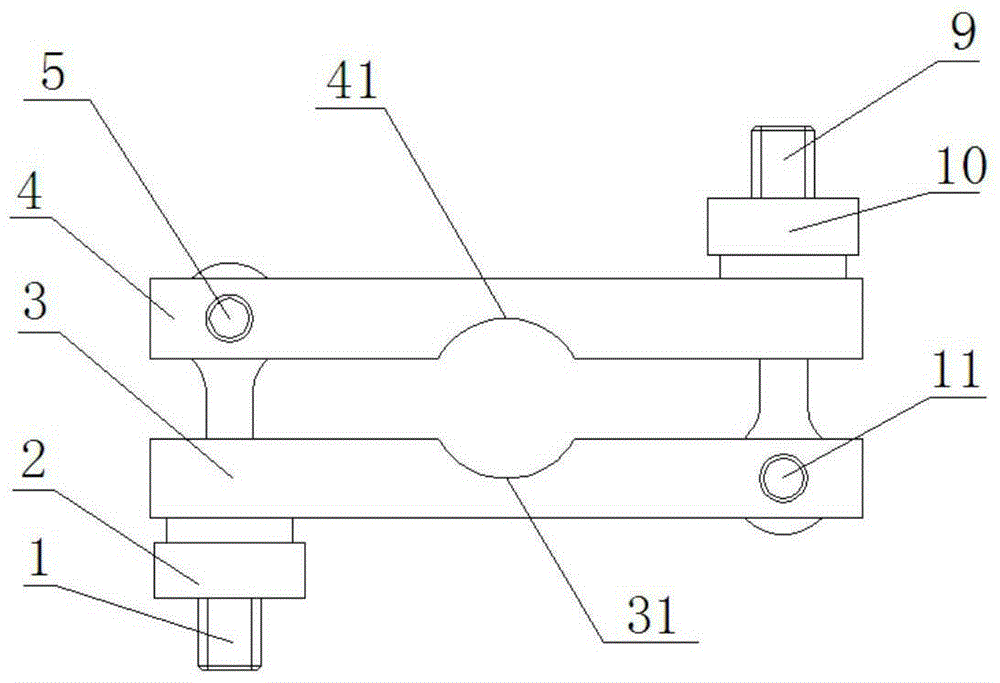
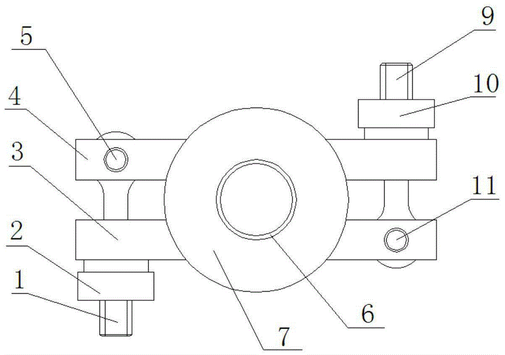
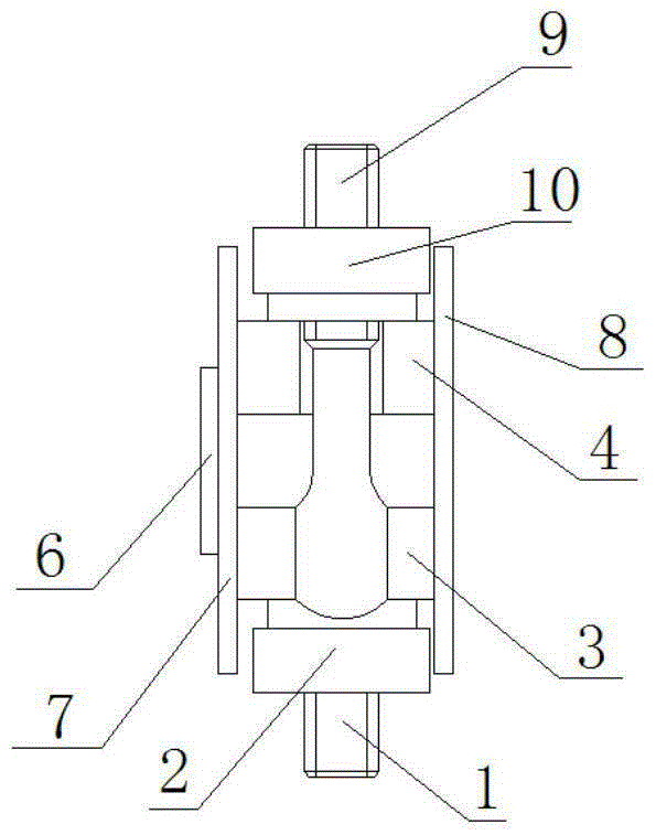
[0018] Such as Figure 1 to Figure 4 A rolling riveting jig shown includes movable bolt A1, lock nut A2, pad M3, pad N4, pin B5, movable bolt B9, lock nut B10 and pin A11; said pad M3 and pad N4 is respectively provided with a card slot M31 and a card slot N41, and the card slot M31 is opposite to the card slot N41; the left end of the spacer M3 and the spacer N4 are connected by a movable bolt A1, and one end of the movable bolt A1 is connected by a pin B5 It is movable installed on the pad N4, and the other end is placed in the slot at the left end of the pad M3, and the end is also covered with a lock nut A2; the right end of the pad M3 and the pad N4 are connected by a movable bolt B9, One end of the movable bolt B9 is movably mounted on the pad M3 through the pin A11, and the other end is placed in the slot at the right end o...


PUM


Abstract

The invention provides a grinding and riveting clamp. A clamping groove M and a clamping groove N are formed in a cushion block M and a cushion block N respectively and are opposite. The left end of the cushion block M and the left end of the cushion block N are connected through a movable bolt A. One end of the movable bolt A is movably arranged on the cushion block N through a pin B, and the other end of the movable bolt A is arranged in a clamping groove in the left end of the cushion block M and sleeved with a locking nut A. According to the grinding and riveting clamp, the two ends of the cushion block M and the two ends of the cushion block N are locked and fixed through screws and nuts instead of manual work, and therefore the operation dangers are reduced for operators. A gap is reserved between the cushion block M and the cushion block N. After the locking nut is released, the cushion blocks are separated when force is exerted through the gap between the two cushion blocks so that a part can be taken out, and the problem that the cushion blocks can not be easily taken out is solved. The clamp is simple in structure and easy to machine, workpieces can be more easily and rapidly assembled and disassembled when the grinding and riveting clamp is used on a bench drill device, and the production efficiency is improved.

Description

technical field [0001] The invention relates to the technical field of riveting, in particular to a riveting jig. Background technique [0002] The coil frame is composed of upper and lower end pieces and a liner. The liner and the end pieces are connected by riveting. During the riveting process, two pads are used to clamp the liner and fix the two end pieces. the distance between. Since the two pads of the riveting jig are combined and fixed by manpower, the pads need to be pressed and fixed manually during riveting. When in use, due to the great force of rotating riveting, and the liner also needs to be clamped, it is dangerous for the operator to operate, and after riveting, the pad is stuck between the two end pieces and it is inconvenient to take out. It is more laborious, and it is necessary to improve the clamping method of the liner. Contents of the invention [0003] In order to solve the above technical problems, the present invention provides a riveting jig,...

Claims


Application Information

Patent Timeline
Patent Type & Authority Applications(China)
IPC IPC(8): B21J15/42
CPCB21J15/42
Inventor 朱丽
Owner GUIZHOU TIANYI ELECTRICAL
Learn More