Magnet device and magnetic resonance imaging device
A technology of magnet device and magnetic yoke, which can be used in measurement devices, measurement of magnetic variables, medical science, etc., and can solve problems such as uneven magnetic field intensity
- Summary
- Abstract
- Description
- Claims
- Application Information
AI Technical Summary
Problems solved by technology
Method used
Image
Examples
no. 1 approach
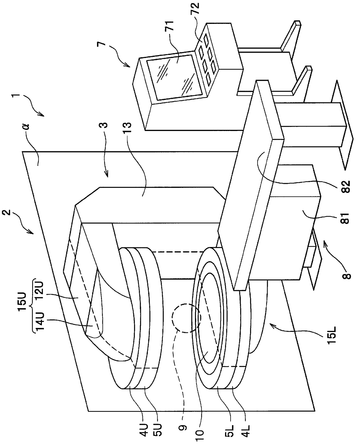
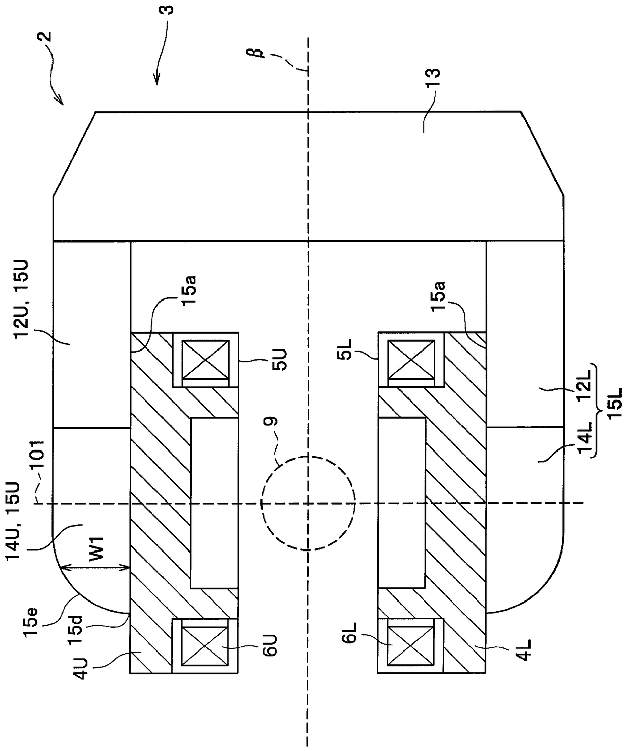
[0046] figure 1 A perspective view of a magnetic resonance imaging apparatus (MRI apparatus) 1 according to a first embodiment of the present invention is shown. The MRI apparatus 1 has: a magnet device 2 that generates a static magnetic field with uniform magnetic field strength in the imaging space 9; a bed 8 that transports the subject to the imaging space 9 in a supine state; and a magnet device 2, the bed 8, etc. The entire MRI apparatus 1 is controlled, and the control unit 7 acquires images representing the physical and chemical properties of the subject by utilizing the nuclear magnetic resonance phenomenon generated when the subject is irradiated with high-frequency pulses.
[0047]The control unit 7 is connected to the magnet device 2, the bed 8, and the like. The control unit 7 has an operation unit 72 that can be operated by an operator to adjust the control content thereof, and a display unit 71 that displays an acquired image. The operation unit 72 accepts oper...
no. 2 approach
[0064] Figure 9 A perspective view showing the upper half of the yoke 3 of the magnet device according to the second embodiment of the present invention. The point of difference between the second embodiment and the first embodiment lies in the shape of the yoke 3, among them the shape of the horizontal front end portion 14U of the yoke. The outer surface 15e of the horizontal front end portion 14U of the yoke in the first embodiment is formed using a curved surface, whereas the outer surface 15e of the horizontal front end portion 14U of the yoke in the second embodiment is formed using a plurality of inclined surfaces with different inclination angles.
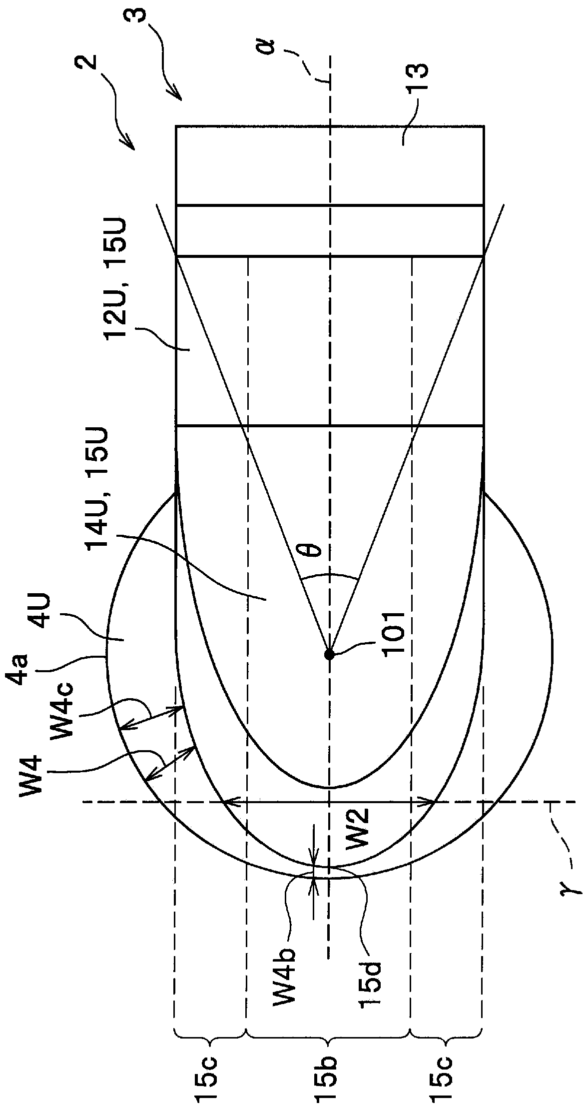
[0065] Figure 10A plan view of a magnet device 2 according to a second embodiment of the present invention is shown. The horizontal front end portion 14U of the yoke has a tapered shape. Specifically, the width W2 in the normal direction of the vertical symmetry plane α decreases in two stages as it approaches the front...
no. 3 approach
[0071] Figure 13 A perspective view showing the upper half of the yoke 3 of the magnet device according to the third embodiment of the present invention. The difference between the third embodiment and the second embodiment lies in the shape of the yoke 3 , which is also the shape of the yoke vertical portion 13 . In the second embodiment, the yoke vertical portion 13 is one column, while in the third embodiment it is a plurality of columns (in Figure 13 2 in the example). Accordingly, a pipe connecting the coil storage containers 5U and 5L, wiring connecting the superconducting coils 6U and 6L, a refrigerator, and the like can be provided between the plurality of adjacent yoke vertical portions 13 . By arranging pipes, wiring, and the like in the area between adjacent yoke vertical portions, the area through which the bed 8 passes can be enlarged and the degree of freedom of movement of the bed 8 can be ensured more widely. In addition, by providing a refrigerator betwee...
PUM
 Abstract
Description
Claims
Application Information
 - R&D
- Intellectual Property
- Life Sciences
- Materials
- Tech Scout
- Unparalleled Data Quality
- Higher Quality Content
- 60% Fewer Hallucinations
Browse by: Latest US Patents, China's latest patents, Technical Efficacy Thesaurus, Application Domain, Technology Topic, Popular Technical Reports.
© 2025 PatSnap. All rights reserved.Legal|Privacy policy|Modern Slavery Act Transparency Statement|Sitemap|About US| Contact US: help@patsnap.com


