Eureka AIR delivers breakthrough ideas for toughest innovation challenges, trusted by R&D personnel around the world.

Reference current compensation method and circuit for DAC

A reference current and current compensation technology, applied in the direction of adjusting electrical variables, control/regulation systems, instruments, etc., can solve problems such as new errors, and achieve the effect of eliminating nonlinear errors

Inactive Publication Date: 2015-12-30
NO 47 INST OF CHINA ELECTRONICS TECH GRP
View PDF3 Cites 6 Cited by
  • Summary
  • Abstract
  • Description
  • Claims
  • Application Information

AI Technical Summary

Problems solved by technology

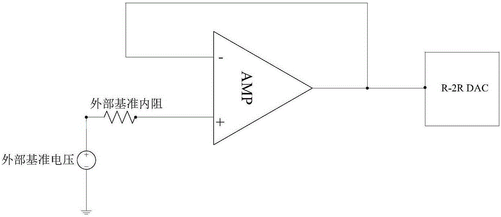
However, the voltage follower is not ideal and will generate offset voltage. Therefore, the method of adding a buffer will generate more serious new errors while eliminating nonlinear errors.

Method used


Image

  • Reference current compensation method and circuit for DAC
  • Reference current compensation method and circuit for DAC
  • Reference current compensation method and circuit for DAC

Examples


Embodiment Construction

[0024] The present invention will be further described below in conjunction with the drawings.

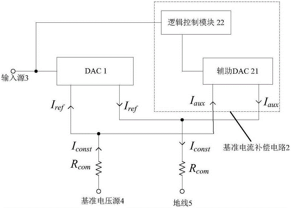
[0025] figure 2 It is a schematic diagram of the structure of the reference current compensation circuit for compensating the reference current of the DAC according to an embodiment of the present invention. Such as figure 2 As shown, the circuit structure includes a DAC1 and a reference current compensation circuit 2 for DAC1, as well as an input source 3, a reference voltage source 4 and a ground wire 5. The reference current compensation circuit 2 includes an auxiliary DAC 21 and a logic control module 22. The auxiliary DAC21 and DAC1 are arranged in parallel between the reference voltage source 4 and the ground line 5. One end of the logic control module 22 is connected to the input source 3 and the other end is connected to the auxiliary DAC 21. The logic control module 22 includes a processor 221 and a memory 222.

[0026] image 3 Yes figure 2 The circuit structure diagram ...


PUM


Abstract

The invention provides a reference current compensation method for a DAC. The reference current compensation method comprises the following steps: arranging a current compensation unit and the DAC between a reference voltage source and a ground wire in parallel; acquiring an input signal, and determining dynamic reference current of the DAC according to the acquired input signal; generating dynamic compensation current corresponding to the dynamic reference current by the current compensation unit so as to combine the dynamic compensation current with the dynamic reference current into constant current. The invention further provides a reference current compensation circuit for the DAC. The reference current compensation circuit comprises the current compensation unit and a logic control module. According to the method and the circuit which are provided by the invention, the reference current flowing through an internal resistor of the reference voltage source can be compensated, so that a pressure drop generated on the internal resistor is fixed, thereby eliminating an error caused by the change of the reference current.

Description

Technical field [0001] The present invention relates to a digital-to-analog converter (DAC), in particular to a reference current compensation method and circuit for the DAC. Background technique [0002] DAC, especially R-2R digital-to-analog converter, has a simple structure, a small number of devices, and can achieve higher resolution, so it is widely used in industrial control fields such as programmable logic control and temperature control. However, when the input signal of the R-2R digital-to-analog converter changes, the reference current in the R-2R resistor network will change as the input code changes. Therefore, the voltage drop generated on the internal resistance of the external power supply will vary with the change of the input signal, resulting in nonlinear errors. [0003] To solve this problem, the traditional method is to add a buffer at the connection between the R-2R resistor network and the reference source and with the ground. Such as figure 1 Shown is a s...

Claims


Application Information

Patent Timeline
IPC IPC(8): G05F1/56
Inventor 王鹏
Owner NO 47 INST OF CHINA ELECTRONICS TECH GRP
Why Eureka
Eureka Blog
Learn More