
LCD panel

A technology of liquid crystal display panels and color film substrates, applied in nonlinear optics, instruments, optics, etc., can solve the problems of large-view angle deviation, reduce the thickness of the box, improve display quality, and improve the problem of large-view angle deviation Effect

Active Publication Date: 2018-05-01
WUHAN CHINA STAR OPTOELECTRONICS TECH CO LTD
View PDF5 Cites 0 Cited by
  • Summary
  • Abstract
  • Description
  • Claims
  • Application Information

AI Technical Summary

Problems solved by technology

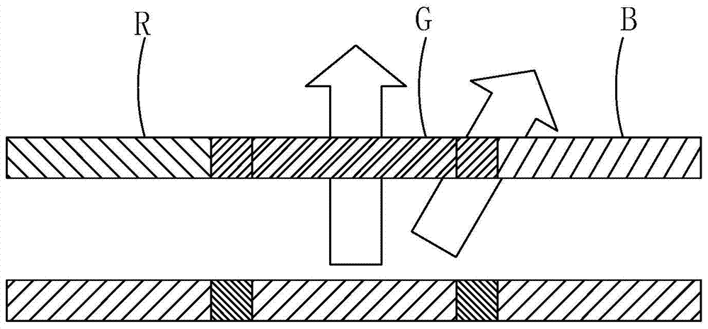
[0006] When the user is watching the display screen of the display device, such as image 3 As shown, if you squint to the left, part of the light may be slanted from the array substrate side of the green sub-pixel area G, and pass through the blue sub-pixel area B to the human eye, then the user will see the mixed light on the green screen. There is a part of blue, so it produces a large viewing angle

Method used


Image

  • LCD panel
  • LCD panel
  • LCD panel

Examples


Embodiment Construction

[0032] In order to further illustrate the technical means adopted by the present invention and its effects, the following describes in detail in conjunction with preferred embodiments of the present invention and accompanying drawings.

[0033] see Figure 4 , is a schematic diagram of the first embodiment of the liquid crystal display panel of the present invention. The liquid crystal display panel provided by the first embodiment includes: a color filter substrate 100 and an array substrate 200 disposed opposite to each other, and interposed between the color filter substrate 100 and the array substrate. A liquid crystal layer (not shown) between the substrates 200;

[0034] The color filter substrate 100 includes a first base substrate 1, and a color-resist layer 2 and a black matrix 3 disposed on the first base substrate 1; Resisting block 20, wherein, described several color resisting blocks 20 comprise red photoresisting block 21, green photoresisting block 22 and blue ...


PUM

PropertyMeasurementUnit
widthaaaaaaaaaa

Abstract

The present invention provides a liquid crystal display panel, by setting the distance between the pixel electrodes corresponding to the green photoresist block and the pixel electrodes corresponding to the adjacent red and blue photoresist blocks to be greater than the distance between the pixel electrodes corresponding to the red photoresist block and the blue photoresist block. The spacing between the pixel electrodes corresponding to the blocking block is equivalent to expanding the distance between the green sub-pixel and the adjacent blue sub-pixel and red sub-pixel in the liquid crystal display panel, thereby reducing the distance corresponding to the red and blue sub-pixels. The chance of the background light diverging into the green sub-pixel reduces the amount of green light mixed around the red and blue screens; it can also further reduce the cell thickness of the liquid crystal display panel corresponding to the green photoresist block, thereby further reducing the corresponding The amount of background light diverging from the red and blue sub-pixels into the green sub-pixels reduces the amount of green light mixed around the red and blue screens, improves the problem of large viewing angle deviation of the liquid crystal display panel, and improves the display quality.

Description

technical field [0001] The invention relates to the field of display technology, in particular to a liquid crystal display panel. Background technique [0002] A Liquid Crystal Display (LCD) has many advantages such as a thin body, power saving, and no radiation, and has been widely used. Such as: LCD TV, mobile phone, personal digital assistant (PDA), digital camera, computer screen or notebook computer screen, etc., occupy a dominant position in the field of flat panel display. [0003] A liquid crystal display panel is usually composed of a color filter substrate (Color Filter Substrate, CFSubstrate), a thin film transistor array substrate (Thin Film Transistor Array Substrate, TFTArray Substrate), and a liquid crystal layer (Liquid Crystal Layer) arranged between the two substrates. Composition, its working principle is to control the rotation of the liquid crystal molecules in the liquid crystal layer by applying a driving voltage on the two glass substrates, and refra...

Claims


Application Information

Patent Timeline
Patent Type & Authority Patents(China)
IPC IPC(8): G02F1/1335G02F1/1343
CPCG02F1/133512G02F1/133514G02F1/134309G02F1/134345G02F1/133519
Inventor 彭海波李得俊
Owner WUHAN CHINA STAR OPTOELECTRONICS TECH CO LTD
Learn More