
Electromagnetic valve of automatic gearbox

A technology for automatic transmissions and solenoid valves, applied in sliding valves, valve details, valve devices, etc., can solve problems such as increasing the difficulty of structural design and space design, making it difficult to ensure product quality stability, and increasing the response time of oil pressure complementarity, etc. To achieve the effect of convenient structure and space design, compact structure and simple structure

Active Publication Date: 2015-12-30
XINGYU ELECTRON NINGBO CO LTD
View PDF8 Cites 4 Cited by
  • Summary
  • Abstract
  • Description
  • Claims
  • Application Information

AI Technical Summary

Problems solved by technology

[0005] 1. Combining the solenoid valve with the pressure storage structure on the automatic transmission has certain hysteresis defects, which increases design difficulty and wastes design space, because the response of the solenoid valve itself is fed back to the automatic transmission through the oil circuit. The pressure storage structure stores the pressure, and after the solenoid valve responds, the pressure storage structure replenishes the oil pressure to the solenoid valve, so it takes a corresponding time, which increases the response time of oil pressure complementation, which easily leads to slow shifting speed
[0006] 2. The separate design of the solenoid valve and the pressure storage structure requires that the solenoid valve and the gearbox pressure storage structure cooperate and coordinate well, which increases the difficulty of structural design and space design
[0007] 3. If the solenoid valve and the pressure storage structure are designed separately, it is difficult to ensure the quality stability of the product, and it is also difficult to quickly assemble it for testing, resulting in inconvenience for product testing

Method used


Image

  • Electromagnetic valve of automatic gearbox
  • Electromagnetic valve of automatic gearbox
  • Electromagnetic valve of automatic gearbox

Examples


Embodiment Construction

[0030] The present invention will be further described in detail below in conjunction with the accompanying drawings and embodiments.

[0031] Such as Figure 1 to Figure 6 Shown is the structural representation of the present invention,

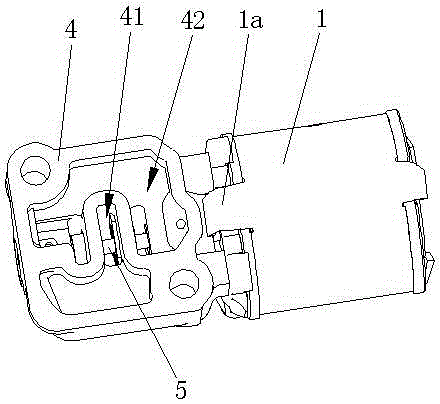
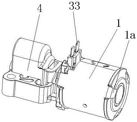
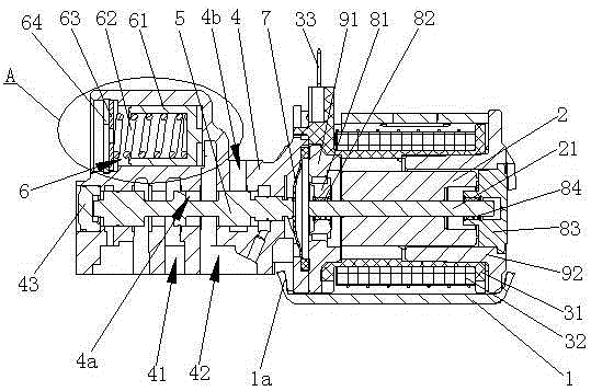
[0032] The reference signs are: shell 1, press button 1a, moving iron core 2, ejector rod 21, electromagnetic coil assembly 3, coil bobbin 31, enameled wire winding 32, electric insert 33, valve body 4, pressure chamber 4a, unloader Pressure port 4b, pressure inlet 41, pressure outlet 42, sealing cover 43, valve core 5, oil film groove 5a, pressure storage chamber 6, piston 61, bump 61a, spring 62, gasket 63, retaining spring 64, rubber pad 7 , Front baffle 81, first bearing 82, rear baffle 83, second bearing 84, front cover 91, rear cover 92.

[0033] Such as Figure 1 to Figure 6 as shown,

[0034] A solenoid valve for an automatic transmission, comprising a casing 1, a moving iron core 2 and an electromagnetic coil assembly assembled ...


PUM


Abstract

The invention discloses an electromagnetic valve of an automatic gearbox. The electromagnetic valve comprises an outer housing, a movable iron core and an electromagnetic coil component assembled inside the outer housing, wherein the movable iron core is assembled at the center of the electromagnetic coil component; an ejector rod is arranged at the center of the movable iron core; a valve body is assembled at the front part of the outer housing; a pressure inlet and a pressure outlet are formed in the valve body; a pressure cavity is formed in the valve body; a valve element is arranged inside the pressure cavity; the front end of the ejector rod is matched with the valve element; a pressure storage chamber is further arranged inside the valve body, and is communicated with the pressure cavity; a piston, a spring, a gasket and a clamp spring are arranged inside the pressure storage chamber; one end of the spring is propped against the gasket, and the other end of the spring is propped against the piston; the clamp spring is placed on the outer side of the gasket, and is in clamping fit with the valve body. The electromagnetic valve has the advantages that the structure is simple, and the stability is good; besides, the electromagnetic valve is integrated with the pressure storage structure, so that the defect of the lag of oil pressure adjustment is eliminated, and the adjustment is more sensitive.

Description

technical field [0001] The invention relates to a component of an automatic transmission, in particular to a solenoid valve of an automatic transmission. Background technique [0002] The gearboxes used in automobiles are gradually replaced by automatic gearboxes, especially in mid-to-high-end cars, almost all automatic gearboxes are used. To realize the automatic shifting of the gearbox, the solenoid valve is an indispensable part and one of the most important parts. [0003] The pressure characteristic curve of the oil circuit is adjusted and controlled by the solenoid valve to meet the oil pressure adjustment and shifting functions of the gearbox. Rely on the vehicle speed and engine speed to feed back the signal to the solenoid valve of the automatic transmission to control the oil circuit, and realize the shift function through the control of the oil pressure of the oil circuit. The solenoid valve of the automatic transmission is installed inside the automatic transmi...

Claims


Application Information

Patent Timeline
Patent Type & Authority Applications(China)
IPC IPC(8): F16H61/02F16K31/06F16K3/314
CPCF16H61/0251F16H2061/0034F16H2061/0253F16K3/314F16K31/0668F16K31/0675F16K31/0696
Inventor 翁国均王波黄国建毛杨榕余文理翁杭秦
Owner XINGYU ELECTRON NINGBO CO LTD
Learn More