
Tool-type cantilever beam and construction method thereof

A tool-type, cantilever beam technology, applied in the direction of house structure support, house structure support, scaffolding accessories, etc., can solve the problems of waste, complicated steel installation, large materials, etc., to save installation costs, increase installation speed, reduce Effect of Material Amount

Inactive Publication Date: 2015-12-30
THE THIRD CONSTR & ENG OF CCFED
View PDF6 Cites 8 Cited by
  • Summary
  • Abstract
  • Description
  • Claims
  • Application Information

AI Technical Summary

Problems solved by technology

[0003] Most of the external protection of the project adopts section steel cantilevered scaffolding. The traditional erection method will cause more section steel crossings inside the building at the yin and yang corners, and it is difficult to locate the steel beams and embedded rings, resulting in complicated installation of section steel and difficult construction; The length of the profiled steel in the concave and convex parts is different, so the construction personnel on the project will cut the profiled steel (generally, the length of the profiled steel is 6m or 9m)
This approach not only increases the difficulty and time of construction operation, but also the cut section steel cannot be used in other parts or other projects, resulting in a large waste of materials

Method used


Image

  • Tool-type cantilever beam and construction method thereof
  • Tool-type cantilever beam and construction method thereof
  • Tool-type cantilever beam and construction method thereof

Examples


Embodiment Construction

[0015] The present invention will be described in further detail below in conjunction with the accompanying drawings, but not as any limitation to the present invention.

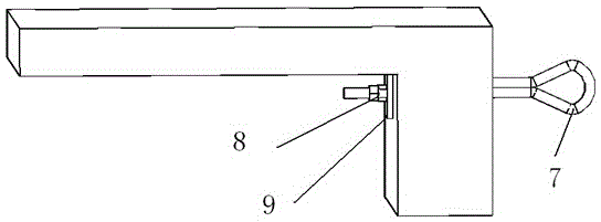
[0016] Embodiment of the present invention: a construction method of a tool-type cantilevered steel beam. When a building structure needs to be installed with a lifting scaffold, a side-by-side pre-buried hole is arranged at the corresponding outer wall of each floor of the building structure, and an I-beam is used as a tool The main body of the type cantilever beam is provided with a support plate at one end of the I-beam, and the connection hole corresponding to the position of the support plate and the position of the embedded hole is used. The bolts are inserted into the connection hole and the embedded hole to realize the vertical fixation of the tool type cantilever beam. On the outer wall of the corresponding floor of the building structure, a positioning rod connected and fixed to the lifting scaffold...


PUM


Abstract

The invention discloses a tool-type cantilever beam and a construction method thereof. A support plate is arranged at one end of joist steel and is vertical to the joist steel; a connection hole which corresponds to the position of an embedded hole in a building external wall is formed in the support plate; the embedded hole is connected with the connection hole through a bolt I, so that vertical fixing of the joist steel on the building external wall is achieved; a locating rod is arranged on the upper surface of the joist steel; a connecting rod is arranged on the lower surface of the joist steel; a flying ring is arranged right above the support plate; the flying ring is connected with the connecting rod through a wire rope. According to the tool-type cantilever beam, the problems that a plurality of profile steel intersections are formed at the parts of internal and external corners in a cantilever scaffold joist steel mounting process, a steel beam and an embedded ring are difficult to locate and the joist steel beam is difficult to install in the prior art are solved; the problems are effectively solved; the steel beam can be installed at any position; meanwhile, the installation cost of the cantilever beam can also be reduced; the material consumption is reduced; the installation speed is also greatly improved; the condition that the time limit for a project is not affected by installation of the cantilever beam is ensured.

Description

technical field [0001] The invention relates to a tool-type cantilevered steel beam and a construction method thereof, belonging to the technical field of building scaffolding erection. Background technique [0002] With the development of the times, the progress of society, and the application of new techniques and materials in construction and the implementation of new norms, construction facilities and safety protection facilities are gradually advancing towards "toolization, finalization, and standardization". The erection of the cantilevered outer frame is an indispensable safety protection facility in the construction process, and the I-beam is one of the necessary components of the cantilevered outer frame. [0003] Most of the external protection of the project adopts section steel cantilevered scaffolding. The traditional erection method will cause more section steel crossings inside the building at the yin and yang corners, and it is difficult to locate the steel b...

Claims


Application Information

Patent Timeline
Patent Type & Authority Applications(China)
IPC IPC(8): E04G5/04E04G3/18E04G3/28
Inventor 万黔云银克俭张璞红杨俊涛吴德远
Owner THE THIRD CONSTR & ENG OF CCFED
Learn More