Vamp glue spraying device saving application space

A technology for shoe uppers and glue spraying, which is applied in the direction of footwear, application, and bonding shoe parts, etc., and can solve problems such as poor glue spray consistency, inability to apply glue spray, and inaccurate positioning

Inactive Publication Date: 2015-12-30
BLACK GOLD STEEL AUTOMATION TECH FUJIAN
View PDF9 Cites 0 Cited by
  • Summary
  • Abstract
  • Description
  • Claims
  • Application Information

AI Technical Summary

Problems solved by technology

[0006] The invention provides a space-saving shoe upper glue spraying equipment and an automatic shoe upper glue spraying method, the main purpose of which is to overcome the inaccurate positioning, poor glue spray consistency and inability to be applied to shoe surface glue spraying existing in the existing glue spray equipment Defects

Method used


Image

  • Vamp glue spraying device saving application space
  • Vamp glue spraying device saving application space
  • Vamp glue spraying device saving application space

Examples


Embodiment 1

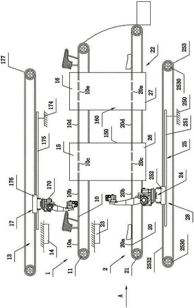
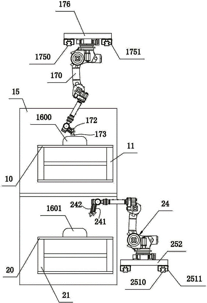
[0031] refer to figure 1 , figure 2 , image 3 and Figure 4. A space-saving automatic production line for footwear, comprising an automatic upper gluing device 1 and an automatic sole gluing device 2 located below the automatic upper gluing device 1, wherein the automatic upper gluing device 1 is The subject to be protected by the present invention is a space-saving shoe upper gluing equipment. The automatic gluing device 1 for shoe uppers and the automatic gluing device 2 for soles are elongated, and are adjacently arranged up and down on the same vertical plane. The automatic gluing device 1 for shoe uppers includes a first conveyor belt 10, a driving The first drive assembly 11 and the first automatic glue spraying control assembly 13 for the first conveyor belt 10 to move at a constant speed, above the first conveyor belt 10 are arranged successively adjacent three-dimensional scanning station 10a, first treatment water spraying station 10b, the first treatment wate...

Embodiment 2

[0050] refer to Figure 5 and Figure 6 . This embodiment is substantially the same as the implementation of Embodiment 1, the difference is that the three-dimensional scanning mechanism 14 in this embodiment includes a shoe upper scanning unit 140, an image processing unit 141, a data acquisition unit 142 and a model generation unit 143, the shoe upper scanning unit 140 is used to take images of the top side of the shoe upper, the left side of the shoe upper, and the right side of the shoe upper, which includes a gantry-shaped bracket arranged at the shoe upper scanning position on the first conveyor belt 10 144, two first cameras 145 are installed on the top of the gantry-shaped support 144, two second cameras 146 are installed on the lower left, two third cameras 147 are installed on the lower right, and the two first cameras 145 are all aimed at the top side of the vamp and are correspondingly used to collect the top side images of the two vamps; the two second cameras 1...


PUM


Abstract

The invention relates to a vamp glue spraying device saving the application space. The vamp glue spraying device comprises a first conveyor belt, a first drive assembly and a first automatic glue spraying control assembly, wherein the first automatic glue spraying control assembly comprises a three-dimensional scanning mechanism, a first treatment water drying mechanism, a first glue drying mechanism and a first multi-workstation hoisting manipulator device, the first multi-workstation hoisting manipulator device comprises a controller, a first six-degree-of-freedom manipulator, a first translation control mechanism, a first spraying gun and a second spraying gun, and the first translation control mechanism comprises a first fixed frame, a first guide assembly, a first movable table and a first transmission assembly. By adopting the vamp glue spraying device, consistency in glue sprayed on each part of a vamp can be guaranteed, so that the waste of the glue is greatly reduced, the consistency of the vamp glue spraying effect is improved, the bonding firmness between the subsequent vamp and a sole is further improved, the service life of shoes is prolonged, and the quality of the shoes is improved.

Description

[0001] This case is a divisional application of the Chinese invention patent application with application number "201410372240.4" and titled "Space-saving shoe upper glue spraying equipment and automatic shoe upper glue spraying method". The filing date of the original application is 2014.07.31. technical field [0002] The invention relates to automatic glue spraying equipment for shoe uppers, in particular to a space-saving shoe upper glue spraying equipment. Background technique [0003] The glue spraying process is a more labor-intensive and time-consuming process in the shoemaking process. The quality of the spray glue determines the firmness of the bonding between the upper and the sole, which in turn affects the performance and quality of the footwear. For now, the existing sole glue spraying is generally by manual operation, which has low production efficiency, unstable quality and high labor cost. Moreover, the adhesive used in shoemaking contains toxic ingredients...

Claims


Application Information

Patent Timeline
Patent Type & Authority Applications(China)
IPC IPC(8): A43D25/18
CPCA43D25/18
Inventor 阙小鸿
Owner BLACK GOLD STEEL AUTOMATION TECH FUJIAN
Why Eureka
Try Eureka