Laser output control method and laser

A laser, laser technology, applied in the field of laser processing, can solve the problems of deformation of the processed object, high peak and power, long output time, etc., to achieve the effect of short output time and low energy

Active Publication Date: 2016-09-28
MAXPHOTONICS CORP
View PDF4 Cites 0 Cited by
  • Summary
  • Abstract
  • Description
  • Claims
  • Application Information

AI Technical Summary

Problems solved by technology

Because in a working cycle of the acousto-optic Q switch, it only outputs a single pulse, the single pulse not only has a single peak value and high power, but also has a relatively long output time. When a single light pulse directly hits the object to be processed, it is easy to cause damage. Heat accumulation near the surface of the processed object causes deformation of the processed object

Method used


Image

  • Laser output control method and laser
  • Laser output control method and laser
  • Laser output control method and laser

Examples


Embodiment Construction

[0020] The present invention will be described in detail below in conjunction with the accompanying drawings and embodiments.

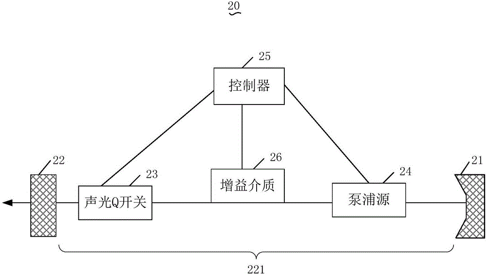
[0021] see figure 1 , the laser 20 includes a high reflectivity reflective fiber Bragg grating 21, a low reflectivity reflective fiber Bragg grating 22, an acousto-optic Q switch 23, a pump source 24, a controller 25 and a gain medium 26, a high reflectivity reflective fiber Bragg grating 21, a low reflectivity reflective fiber Bragg grating The reflective fiber grating 22 and the gain medium 26 form a resonant cavity 221, and the acousto-optic Q switch 23 and the pump source 24 are all arranged in the resonant cavity 221, and the controller 25 is connected with the acousto-optic Q switch 23, the pump source 24 and the gain medium 26 respectively. connect.

[0022] The pumping source 24 is used to input pumping light into the resonant cavity 221. The gain medium 26 is used for storing the pump light and accumulating the number of energy level invers...


PUM


Abstract

The invention discloses a control method for laser device output, and a laser device. The method comprises the steps: inputting pumping light into a resonant cavity of the laser device; increasing driving voltage of an acousto-optic Q switch of the laser device and / or driving current of a pumping source of the laser device in a process that a gain medium of the laser device absorbs and stores energy-level inversion population on pumping light accumulation laser to enable the laser device to meet oscillation starting conditions before the driving voltage of the acousto-optic Q switch reaches the maximum bearing voltage of the acousto-optic Q switch to output a first light pulse; and further increasing the driving voltage of the acousto-optic Q switch and / or the driving current of the pumping source in the work period of the acousto-optic Q switch to enable the laser device to meet the oscillation starting conditions again before the driving voltage of the acousto-optic Q switch reaches the maximum bearing voltage of the acousto-optic Q switch to output a second light pulse. By using the manner, at least two light pulses are output within a same work period of the acousto-optic Q switch.

Description

technical field [0001] The invention relates to the technical field of laser processing, in particular to a method for controlling the output of a laser and a laser. Background technique [0002] At present, a laser refers to a laser that controls the output of optical pulses through its built-in acousto-optic Q switch. Specifically, the laser makes its resonator in a low-Q state at the beginning of pumping, so that the oscillation in the resonator cannot be generated. When When the number of energy level reversal particles on the laser reaches the maximum value, the driving voltage of the acousto-optic Q switch suddenly rises to the maximum value, and the oscillation in the resonant cavity is quickly established, and the energy level of the laser is reversed in a very short time. The number of particles is consumed and converted into light energy in the resonant cavity, and the energy is released in the form of a single pulse at the output of the resonant cavity, and the pe...

Claims


Application Information

Patent Timeline
Patent Type & Authority Patents(China)
IPC IPC(8): H01S3/117
Inventor 居剑王平成蒋峰
Owner MAXPHOTONICS CORP
Why Eureka
Try Eureka